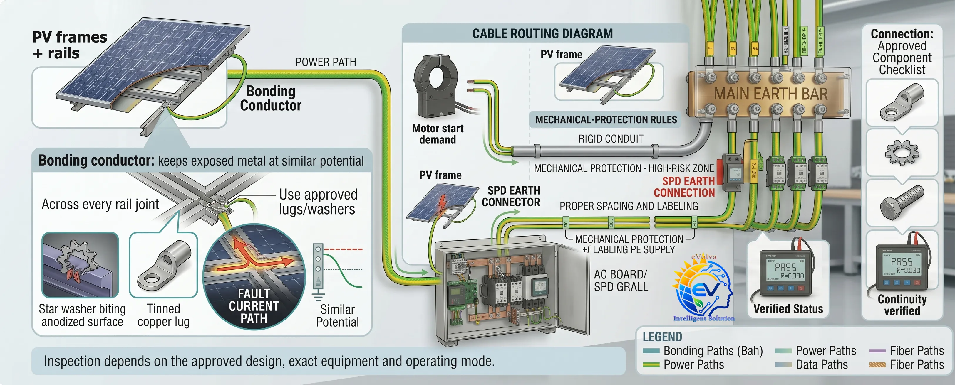
Compare possible reverse current from parallel strings with the module maximum-series-fuse rating and conductor withstand. Record the decision for each string and pole.
Component technical screen
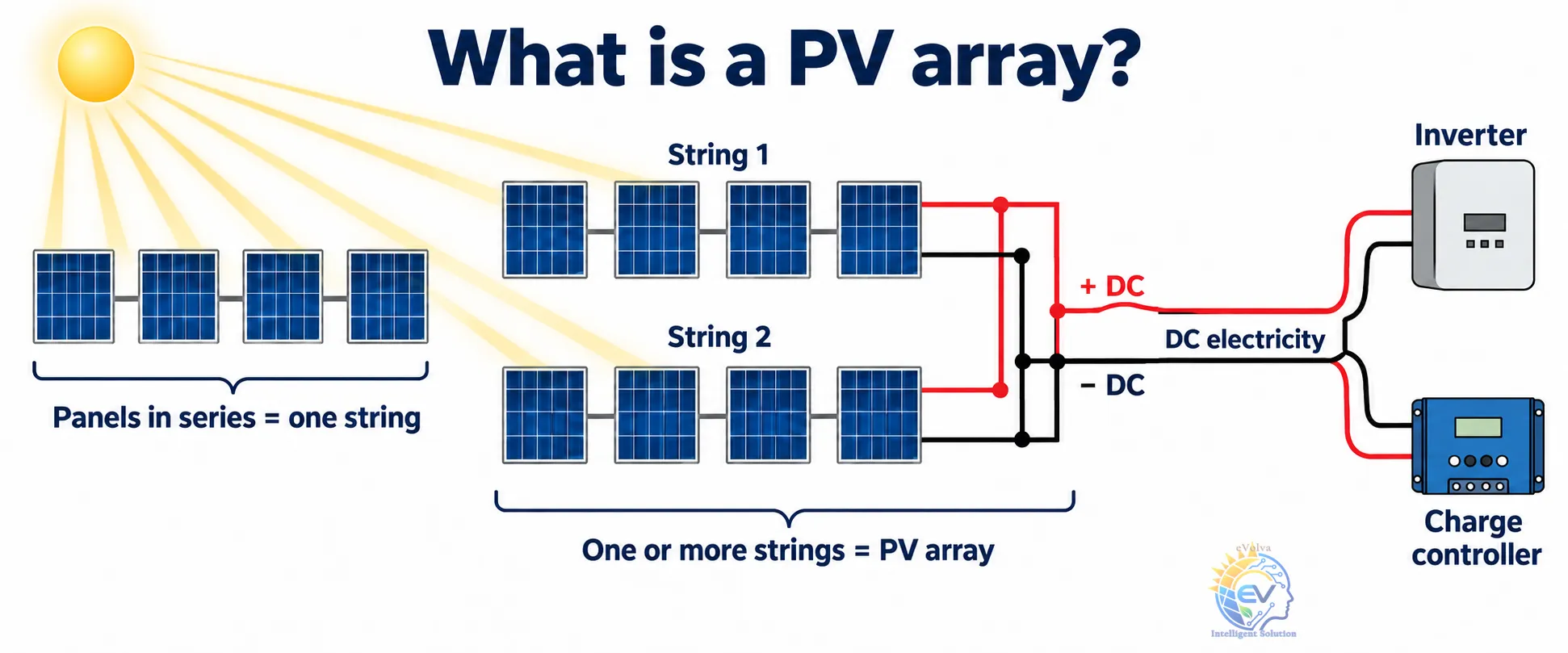
What is a PV array?
PV means photovoltaic: converting sunlight into electricity. A PV array is a group of solar panels connected to work together. Panels connected in series form a string; one or more strings form the array, which supplies DC electricity to an inverter or charge controller.
☀ Sunlight
PV array · two example strings
String 1
String 2
Panels in each string are connected in series.
DC electricity →+ / −
Inverter or charge controller
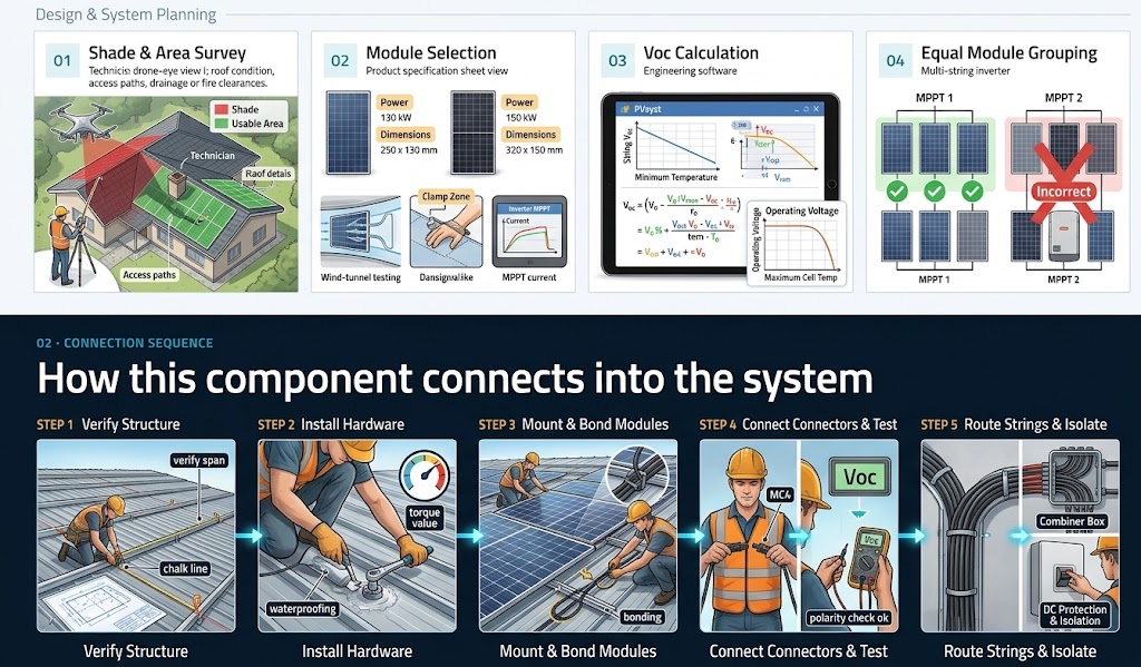
01 · Design basis
What must be decided before installation
PV array planning illustration
From site survey to protected string connection
DC protection illustrated guide
Protect the path from PV strings to inverter
Follow the power path, then inspect the enclosure. The drawings explain device roles; the approved single-line diagram determines the actual wiring, ratings and pole arrangement.
Click image to view at 100%
Click image to view at 100%
Choose a PV-rated SPD with Ucpv above the calculated maximum string Voc. Coordinate Type 1/Type 2 with the lightning design and keep DC and PE connections short and direct.
Use a PV DC-rated, lockable switch-disconnector with a voltage, current and pole configuration suitable for the system. Verify that its OFF position isolates the intended circuit.
Match IP, UV and temperature ratings to the location. Separate conductors, use suitable glands, label both ends, and leave access for fuse and SPD inspection.
Illustrations are conceptual. PV strings remain live in daylight even when the inverter or AC supply is switched off. Qualified personnel must follow the approved design, device manuals and local rules.
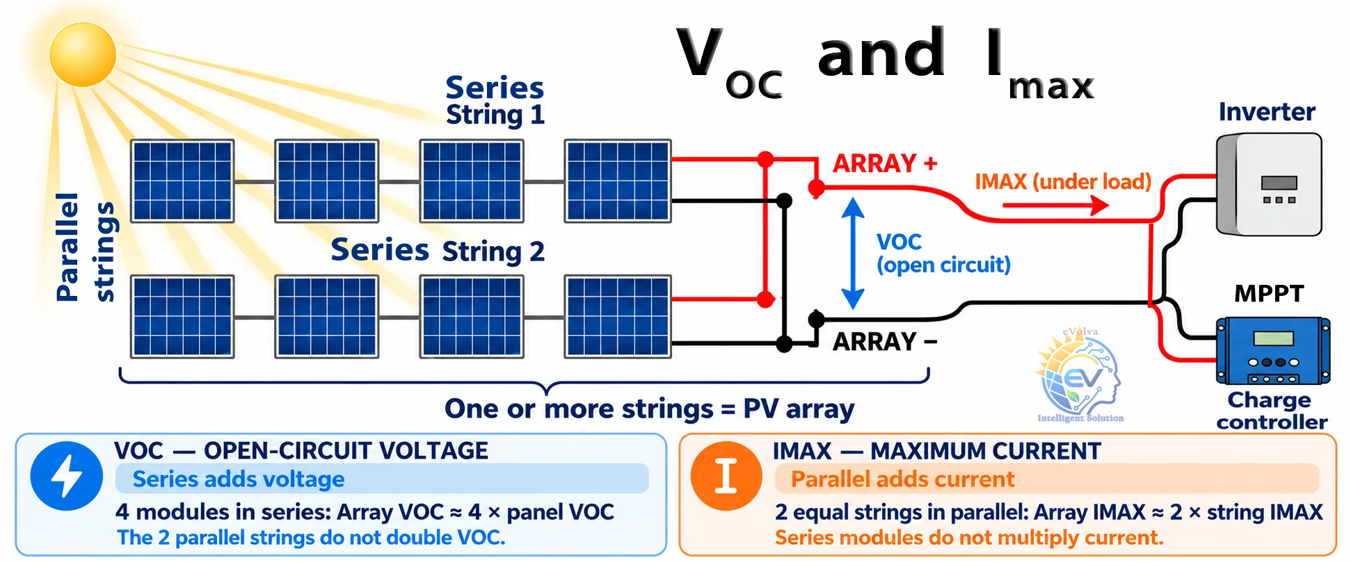
02 · Connection sequence
How this component connects into the system
03 · Equipment schedule
Typical equipment, accessories and selection rules
| Item | Purpose | Selection / connection rule |
|---|
Firmware settings & commissioning — installer guide
Before setup · Identify the equipment and gather the documents
- Photograph the nameplate and record manufacturer, exact model/variant, serial number, rated voltage/phase and installed firmware versions.
- Obtain the matching installation and user manuals, either printed or from the official manufacturer website. Check model, region, revision/date and firmware applicability; keep an offline copy at the site. A similar model’s manual may have different wiring and settings.
- Collect the battery manual, approved inverter–battery compatibility list, BMS protocol/cable instructions and any required firmware combination. For an inverter without batteries, mark these checks as not applicable.
- Have the approved single-line diagram, PV string calculations, cable/protection design, earthing/transfer arrangement and utility connection/export requirements available. Confirm that the installed equipment matches these documents.
- Confirm installer access and authorization for protected menus. Save or photograph the existing settings and fault log before changes; record each change, its reason and the document supporting it. Follow the manual’s isolation and commissioning procedure.
- If the exact manual, approved profile or compatibility evidence is missing, resolve it with the manufacturer or authorized supplier before entering uncertain values. Plan the operating-mode tests and owner handover before energizing.
Use this guide to understand and document the settings. All numerical examples are illustrative planning calculations; select actual values from the exact inverter and battery instructions, the approved design and utility requirements. Menu names vary by model and firmware.
1 · Model, firmware and battery protocol
Identify the exact inverter variant, region, firmware versions and battery model. Select the approved battery communication protocol and confirm that the inverter reads SOC, temperature and permitted charge/discharge current. A working display alone does not prove communication is correct.
Example: two batteries with the same 51.2 V nominal voltage may use different CAN/RS485 protocols. Use the approved model, cable pinout, address and termination arrangement. Record the configuration and confirm the specified response if communication is lost.
2 · Grid profile and protection
The country/grid profile controls connection rules, voltage and frequency protection, reconnection and other grid functions. Select the profile approved for the installation and utility. Protection thresholds and delays must come from the approved requirements; changing them to stop nuisance trips can create an unsafe or unauthorized connection.
Example: a US split-phase manual is not a settings template for a Myanmar installation. If the grid repeatedly disconnects, log measured voltage/frequency and investigate supply conditions and wiring before seeking an approved setting change. Record the active profile and test reconnection according to the commissioning procedure.
3 · Charge and discharge limits
Set current and power limits within the battery instructions, live BMS limits, inverter capability and cable/protection design. Check whether a menu value means battery DC current, AC input current, or charging power. These are different quantities. Temperature and SOC can make the BMS reduce its limits during operation.
Example: at 51.2 V, 50 A represents about 2.56 kW of DC charging power (V × A ÷ 1,000). Actual voltage changes, and AC input power is higher because of conversion losses. A battery permitting 50 A must not be assigned 100 A simply because the inverter supports it. Verify actual current and BMS status while charging and discharging.
4 · SOC reserve, shutdown and restart
Minimum SOC preserves a reserve for outages; shutdown protects the battery at its operating boundary. Restart settings determine when loads can reconnect after charging recovers. Use battery and inverter instructions for thresholds and hysteresis, so the system does not repeatedly start and stop. SOC estimates also depend on correct BMS calibration.
Example: a nominal 10 kWh battery used from 90% to 30% SOC has approximately 6 kWh available DC energy. At an assumed 90% conversion efficiency, that is 5.4 kWh AC, or about 5.4 hours at a steady 1 kW load. This is a learning estimate: temperature, ageing, standby use and changing loads reduce or change runtime. Do not apply an additional DoD factor to the same SOC window.
5 · Energy priority and operating mode
Confirm what self-consumption, backup, time-of-use and any off-grid modes mean on the exact model. Decide when solar serves loads, charges the battery or exports, and when the battery may discharge. A backup reserve may reduce daily savings but retain energy for outages. Some grid inverters cannot supply loads during an outage.
Example: a shop needing evening outage backup may retain a larger reserve than a site focused on daytime self-consumption. Check the power-flow display with solar surplus, solar shortage and grid loss; confirm that the observed behavior matches the documented priority.
6 · Charging schedules and AC source limits
Check clock, time zone, schedule overlap, target SOC and permission for grid charging. Limit charging so the supply or generator can also support connected loads. Generator sizing must consider continuous kW, kVA/power factor, starting demand and manufacturer limits. AC input limiting and battery charge-current limiting may be separate settings.
Example: a source with 5 kW of permitted continuous real power serving 2 kW of loads has less than 3 kW available for AC charging once a suitable operating margin is allowed. Motor starts may require charging to reduce further. Test the combined load and charging condition, and confirm that the schedule resumes correctly after a power interruption.
7 · Export limit, meter and CT
Export control depends on a compatible meter or CT installed at the specified measurement point, with correct direction, phase mapping and communication. Confirm whether the limit applies to the whole site or each phase. Zero-export control may have transient response; it is not an isolation device or a substitute for utility approval.
Example: with PV disabled and a known load operating, the meter should show import in the correct direction. Then introduce PV and change the load to verify control at the connection point. Follow the approved test for meter communication loss and document the fail-safe response; a reversed CT can make the controller act in the wrong direction.
8 · Backup output, transfer and generator
Check backup-output ratings, overload duration, phase imbalance, transfer behavior and generator support. Neutral switching and neutral–earth bonding must follow the electrical design and exact equipment instructions. A menu selection cannot correct incorrect transfer wiring or an unsafe bonding arrangement.
Example: a 5 kW continuous backup output does not automatically start a motor with a much larger starting demand. Test essential loads and intended transfer modes with the approved procedure. Verify protection operation, generator charging and return to grid, including the designed neutral/earth behavior.
9 · Firmware updates and monitoring
Use the manufacturer-approved update for the exact hardware and battery combination. Save settings and version records before changing firmware; follow the specified power and communication conditions. Check release notes for changed defaults or compatibility. Confirm alarms, remote access permissions and owner notifications.
Example: after an update, recheck battery protocol, grid profile, reserve, charging schedules and export control rather than assuming every setting was retained. Use only a manufacturer-supported recovery or rollback process, and repeat the affected commissioning tests.
10 · Installer handover record
For every important setting, record the menu name, final value and unit, reason, source document/version, date and test result. Include model/serial numbers, firmware versions, battery approval, grid profile, current limits, SOC thresholds, schedules, export settings and source-mode tests. Give the owner a clear explanation of normal operation and alarms.
Example record: “Battery charge limit: 50 A DC; source: approved battery manual revision and inverter manual; verified measured current and BMS status; installer/date.” The number is illustrative. Attach screenshots or a configuration export and the signed commissioning results so a later technician can understand the settings.
Worked example · Essential settings for a small hybrid system
Learning scenario: a 5 kW single-phase hybrid inverter, an approved 51.2 V / 200 Ah LiFePO₄ battery, and about 1 kW average essential load. The values below demonstrate the decisions to record. They are not a configuration preset: actual model menus, limits, battery instructions and utility approval govern.
| Setting / decision | Illustrative configuration and verification |
|---|---|
| Equipment record | Record the actual 5 kW single-phase hybrid inverter model, serial number and firmware, plus the approved 51.2 V, 200 Ah battery model and BMS version. Obtain both manuals before configuration. |
| Grid profile | Select the utility-approved profile for this exact model and site. Copy no voltage, frequency or reconnection thresholds from this example; record the approved values and document reference. |
| Battery mode and communication | Select the approved lithium/BMS protocol, cable and addressing arrangement. Confirm live SOC, temperature and charge/discharge limits. Do not substitute lead-acid charging or equalization settings. |
| Charge-current limit | Illustrative limit: 50 A DC, only if the battery, BMS, inverter and cable/protection design all permit it. At nominal 51.2 V this is about 2.56 kW into the battery. Check whether solar and AC charging share a total limit or have separate limits. |
| Discharge-current limit | Illustrative limit: 80 A DC if approved. At nominal 51.2 V that is 4.10 kW DC; assuming 90% conversion efficiency, about 3.69 kW AC before other limits and standby use. A 5 kW inverter does not make the battery capable of 5 kW. Verify limits at the lowest operating voltage. |
| Energy priority and reserve | Example objective: serve loads from solar, charge surplus into the battery, and use the battery down to a 30% grid-connected reserve. Grid supplies the remaining demand. Whether the reserve may be used during an outage is model-specific; document that behavior separately. |
| Target SOC and runtime | Illustrative target: 90% SOC if permitted. Nominal energy is 51.2 × 200 ÷ 1,000 = 10.24 kWh. From 90% to 30%, estimated DC energy is 6.14 kWh; at 90% efficiency a steady 1 kW load runs about 5.53 hours. This is the energy above reserve, not a guaranteed outage runtime. |
| AC charging and generator | Example policy: grid charging disabled unless the owner’s backup plan requires a scheduled top-up. For a generator with 5 kW permitted continuous real power and 2 kW loads, charging must remain below the remaining 3 kW with suitable margin. Select the actual input limit from generator and inverter instructions; allow for motor starts. |
| Export control | If export is prohibited and this model supports approved zero-export control, configure the compatible meter/CT and zero-export mode. Verify import direction with PV off, then test varying PV and loads. Record the documented response to meter communication loss. |
| Backup, shutdown and restart | Put only designed essential circuits on the backup output. Obtain shutdown/restart thresholds, transfer configuration and neutral/earth requirements from the approved design and manuals. Test grid loss, recovery, battery low-SOC behavior and generator operation where used. |
Before handover: save the final configuration, record measured results against each setting, confirm alarms and owner access, and explain which changes require an installer. Repeat affected tests after a firmware update.
Manufacturer references
Growatt SPH 10000TL-HU-US(B) — user manual ↗
This is a US-model reference supplied for learning. Apply its menus and settings only to the matching model; its grid profile and electrical arrangement must not be copied to a Myanmar installation.
04 · Inspection and commissioning
Required checks
05 · Avoid these failures
Common installation mistakes
Engineering references
Standards and handover records
Handover should include approved single-line diagram, calculations, datasheets, certificates, settings, test results, labels, warranties, photographs and as-built cable routes.