Knowledge base · PE / Bonding Cable
PE and Bonding Cable Selection for Solar PV Systems
A solar installation can generate clean power for years, but its protective earthing system has to work in a fraction of a second when a fault occurs. If insulation fails and an energized conductor touches an exposed metal enclosure, the protective conductor provides a low-impedance path for fault current so the protective device can disconnect the supply.
That is why PE and bonding conductor sizes are not selected from the system’s kWp rating or normal operating current. They are selected from the applicable electrical rules, conductor material and installation, fault current, disconnection time, protective-device behavior and equipment requirements.
The right question is not “What earth wire size is typical for this kW system?” It is “Will this conductor safely carry the prospective fault current long enough for the required protection to operate—and does it meet the local installation rules?”
PE, bonding and the earth electrode are different things
These terms are often used interchangeably, but they do different jobs.
| Conductor or connection | Purpose in a solar installation |
|---|---|
| Protective earth conductor (PE) | Connects exposed conductive parts to the installation’s protective earthing system and provides a fault-current path. |
| Main protective bonding | Connects specified extraneous conductive parts to the main earthing terminal (MET) to reduce dangerous potential differences. |
| Supplementary bonding | Locally connects conductive parts where the applicable rules or risk assessment require it. |
| Earthing conductor | Connects the MET or earthing system to an earth electrode. It is sized and installed under the applicable rules. |
| Neutral | A circuit conductor. It is not a PE conductor, and neutral-to-earth connections are made only where the system design and rules specify. |
| Functional earth or DC reference | Used for equipment operation or monitoring when specified. It is not automatically a substitute for protective earthing. |
An earth rod does not replace a required PE conductor. Likewise, bonding a PV module frame does not mean that a PV string’s positive or negative conductor should be connected to earth.
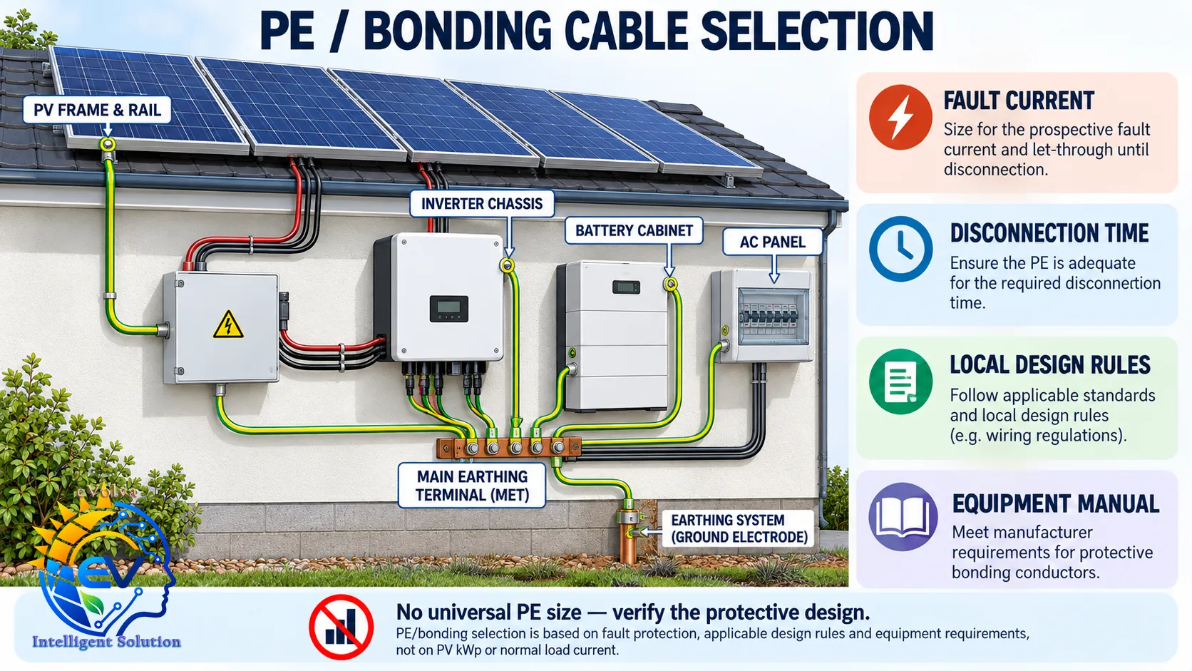
Which solar parts may need bonding?
Start with the local electrical rules and the installation manuals. Depending on the equipment class, array design and earthing arrangement, the design may require connections for:
- PV module frames and mounting rails
- Inverter and combiner-box enclosures
- Battery cabinets and associated metal enclosures
- AC switchboards and distribution enclosures
- Cable trays, metallic conduits or other conductive services, where required
- Surge protective device (SPD) earth terminals and the designated MET
Do not assume every metal part must be bonded, or that every module frame has the same bonding arrangement. Follow the module and racking manufacturer’s instructions, the equipment’s protective class, lightning-protection design and the applicable code. Use listed bonding hardware where specified; paint, anodizing, loose fasteners or incidental contact may prevent a dependable electrical connection.
Keep the PV DC circuit separate from the PE function. Do not bond a PV string conductor or battery negative to PE unless the system architecture, inverter or charge-controller manual and local rules explicitly require that arrangement. Transformerless inverters and some battery systems use particular insulation-monitoring or grounding schemes.
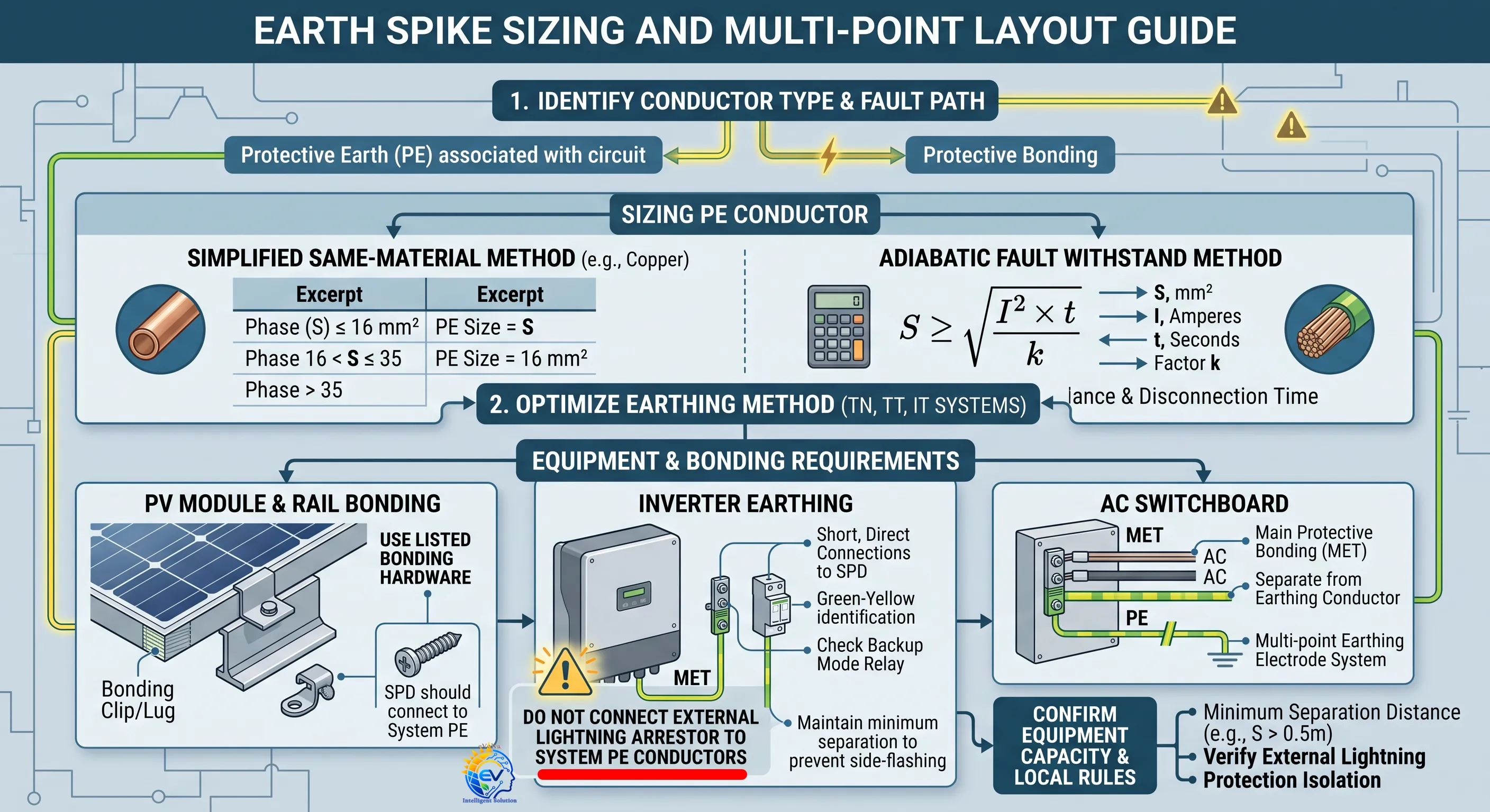
How to select a PE conductor
Use this sequence for each circuit or bonding path.
1. Identify the earthing arrangement and fault source
Establish whether the installation uses a TN, TT, IT or other locally defined arrangement. Identify every operating mode that changes the fault path: utility supply, generator, inverter backup, island operation and battery operation.
The available fault current and disconnection behavior can differ between modes. An inverter may limit fault current; a grid supply may provide much higher current. The design must still achieve the required disconnection and touch-voltage protection in each mode.
2. Identify the protective device and required disconnection
Record the fuse, circuit breaker, RCD or RCBO protecting each circuit. Check its characteristics against the prospective fault current and the earth-fault loop impedance. A PE conductor can survive a short fault thermally and still be inadequate if its impedance is too high for the protective device to disconnect as required.
3. Apply the governing sizing method
IEC-oriented design guides describe two common approaches for a PE associated with circuit phase conductors:
Simplified same-material method — copper example
| Phase conductor cross-section | Reference minimum PE cross-section |
|---|---|
| Up to 16 mm² | Same cross-section as the phase conductor |
| More than 16 mm² up to 35 mm² | 16 mm² |
| More than 35 mm² | Half the phase-conductor cross-section |
This simplified method assumes the PE and phase conductors use the same material. Apply the applicable correction where materials differ, and confirm whether the national rules adopt this method and these limits. If the PE is separate from the phase conductors, IEC-oriented guidance also gives reference minima of 2.5 mm² copper when mechanically protected and 4 mm² copper when not mechanically protected. Local requirements can be different or more stringent.
Adiabatic fault withstand method
For a conductor heated by a short-duration fault, the adiabatic check is:
S ≥ √(I² × t) / k
Where:
- S is the required conductor cross-section in mm²
- I is the fault current flowing through the conductor in amperes
- t is the protective device’s clearing time in seconds
- k depends on the conductor material, insulation and permitted starting and final temperatures
Use the correct fault current and clearing time for the circuit and operating mode. The calculated thermal minimum is only one check: also verify the fault loop, automatic disconnection, mechanical strength, installation method, corrosion exposure and terminal range.
A training example
Suppose a copper AC circuit has a 10 mm² phase conductor. Under the simplified same-material method above, the reference PE cross-section is also 10 mm². That is a starting point for the design calculation—not a universal “10 mm² for solar” rule. The actual selection still needs verification against the protective device, fault path, routing, terminal capacity and local code.
Main and supplementary bonding need their own checks
Main protective bonding is not sized by copying the PV string cable size. An IEC-oriented guide describes the main bonding conductor as generally at least half the cross-section of the largest PE connected to the main earthing terminal, with reference minimums of 6 mm² copper or 10 mm² aluminium and limits beyond which a larger bonding conductor is not generally needed under that guidance. National rules may set different values.
Supplementary bonding is selected for the parts it connects and the local conditions. An IEC-oriented guide relates its minimum cross-section to the associated PE conductors; mechanical protection may also be required. Do not apply the main-bonding rule automatically to module-frame bonds, SPD leads or electrode conductors. Check the relevant installation rule and product instructions for each connection.
Equipment and installation details matter
A correctly calculated conductor can still fail at a poor termination. Before installation, verify:
- The terminal accepts the conductor material, cross-section, strand class and lug type.
- The specified tightening torque is followed, using compatible hardware.
- Bonding washers, clips or listed connectors are installed exactly as instructed.
- Rail joints and removable sections maintain electrical continuity where the design depends on them.
- Outdoor conductors and joints are protected against UV, water ingress, corrosion, abrasion and mechanical damage.
- The PE route is protected and arranged with its associated circuit conductors as required by the wiring rules.
- SPD earth connections are short, direct and arranged to avoid unnecessary loops.
- Green-yellow identification is used where required by local rules; PE is never identified as a normal current-carrying conductor.
For module frames and rails, confirm that the selected clips or lugs are approved for the specific frame and rail materials. Where coatings or dissimilar metals are involved, use the specified corrosion-compatible hardware. Do not rely on a random bolt, hinge or painted joint as the only protective connection.
Check grid, generator and backup modes
Hybrid solar systems need mode-specific checks. During commissioning, verify how the inverter switches line and neutral, where neutral-to-earth bonding is established, and whether an internal bonding relay changes state in island mode. Confirm the RCD or RCBO type and operation against the inverter manufacturer’s instructions and the local rules.
A design that works while grid-connected may behave differently when the inverter is supplying a backup circuit. Check the fault-current path and protective-device operation in each mode the system is designed to support.
For related inverter earthing and Riso topics, see the solar inverter grounding safety guide.
Commissioning and documentation checklist
Before handover, record and verify:
- PE and bonding conductor sizes, material, route and endpoints
- Connections to the MET and any required SPD or equipment earth terminals
- Continuity of protective conductors and bonded metalwork
- Earth electrode measurements where an electrode is part of the design
- Earth-fault loop impedance and protective-device disconnection checks, as applicable
- RCD/RCBO operation in grid and backup modes
- Terminal torque and visual inspection of outdoor connections
- Any insulation-resistance tests, performed only in a way permitted by the equipment manufacturers
- As-built drawings, test results, equipment manuals and changes from the approved design
Accessible and inspectable connections make future maintenance safer. Label the MET clearly and preserve a record of the bonding layout so a later installer can understand what each conductor protects.
Common questions
Is the PE always the same size as the phase conductor?
No. A simplified method relates PE size to phase-conductor size for defined ranges and conditions. The adiabatic method, fault-loop requirements, local rules and equipment instructions can lead to a different result.
Can I choose a PE size from the PV system’s kWp?
No. PV power rating does not determine protective-conductor size. Use the relevant fault-protection design and bonding requirements.
Does an earth rod replace the PE?
No. The electrode and PE have different functions. The complete earthing arrangement and protective device must work together to meet the applicable fault-protection requirements.
Is 6 mm² copper always enough for bonding?
No. Some IEC-oriented guidance lists 6 mm² copper as a minimum for a main equipotential bonding conductor under its conditions. That does not make it a universal size for every PE, PV frame bond, SPD connection or installation. Check the local rules and the circuit or equipment requirements.
Should the PV negative or battery negative be bonded to earth?
Only when the system design, equipment manual and local rules call for it. An unintended DC bond can interfere with insulation monitoring, inverter operation or protection.
The practical rule
Select PE and bonding conductors from the protective design, not from a generic solar cable chart. Confirm the conductor’s thermal fault withstand, fault-loop performance, disconnection time, mechanical protection, connection hardware and behavior in every operating mode. Then test and document the installed system.
The references below are IEC-oriented design sources. The applicable law is the locally adopted electrical code and its current edition; equipment manuals and approved project documents also govern the installation.
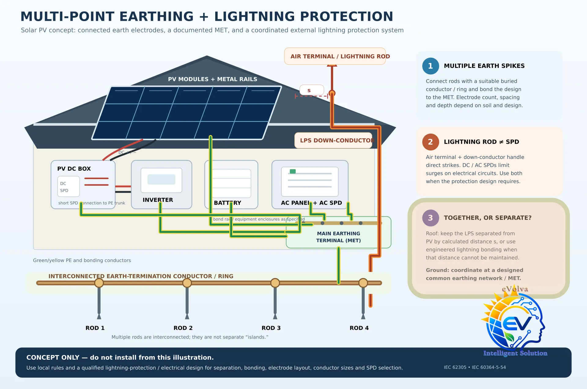
Important Note: earth electrodes and lightning protection
Multiple earth rods are connected by a buried conductor or ring to form one electrode network, coordinated with the main earthing terminal (MET). Rod count, spacing and depth depend on the soil and the site design; there is no universal layout.
By “lightning arrestor,” people may mean either a roof air terminal (lightning rod) or an SPD in the electrical circuit. They are different:
- On the roof: Keep an isolated air terminal and its down-conductor separated from PV frames and cables by the calculated distance
s. If that distance can’t be maintained, a qualified designer must specify lightning bonding and coordinated surge protection. IEC 62305-3 covers LPS design and separation-distance calculations. - At ground level: Coordinate the LPS and electrical earthing through the designed common earthing network/MET; avoid separate, unconnected earth “islands.” An IEC-based guide describes a common earth-termination system as preferred.
- For SPDs: AC and DC SPDs protect electrical circuits; they do not replace the air terminal, PE conductor or LPS. Keep their earth connections short and direct.
Electrical Installation Guide — SPD for photovoltaic applications
References
- IEC 60364-5-54 — Earthing arrangements and protective conductors
- IEC 60364-7-712:2025 — Solar PV power supply installations
- IEC 60364-4-41 — Protection against electric shock
- IEC 60364-5-53 — Devices for protection, isolation, switching, control and monitoring
- Schneider Electric Electrical Installation Guide: Sizing of protective earthing conductor and Equipotential conductor
- The exact inverter, battery, module and mounting-system installation manuals used on the project