Solar PV DC Cable Selection: Sizing, Voltage Drop and Safety
Why solar DC cables matter
PV cables carry power from modules to the inverter or combiner equipment every day the array is operating. The right cable helps deliver the energy the modules produce, keeps insulation within its design limits and reduces avoidable faults over the life of the system.
System kWp alone does not determine cable size. Select every circuit separately using its design current, maximum operating voltage, route length, installation method, ambient temperature, grouping and the equipment manufacturer's requirements.
Energy yield
Cable resistance turns some electrical energy into heat. Longer routes and higher current increase that loss. A suitable conductor cross-section limits voltage drop and helps the inverter receive the array voltage it needs to track the maximum power point.
Safety and reliability
Damaged, overheated or incorrectly rated insulation can cause leakage to earth, insulation-resistance alarms and, in some fault conditions, shock or fire risk. Loose, poorly crimped or incompatible connectors can overheat and arc. Route and terminate DC cables carefully, and use connectors that are explicitly compatible with one another.
Long service life
PV cable is designed and tested for the electrical, thermal and outdoor conditions stated in its product specification. A long service life is not guaranteed by a generic label: verify the cable standard, UV and weathering performance, temperature limits, warranty and installation conditions. Do not assume a general-purpose cable is a safe substitute.
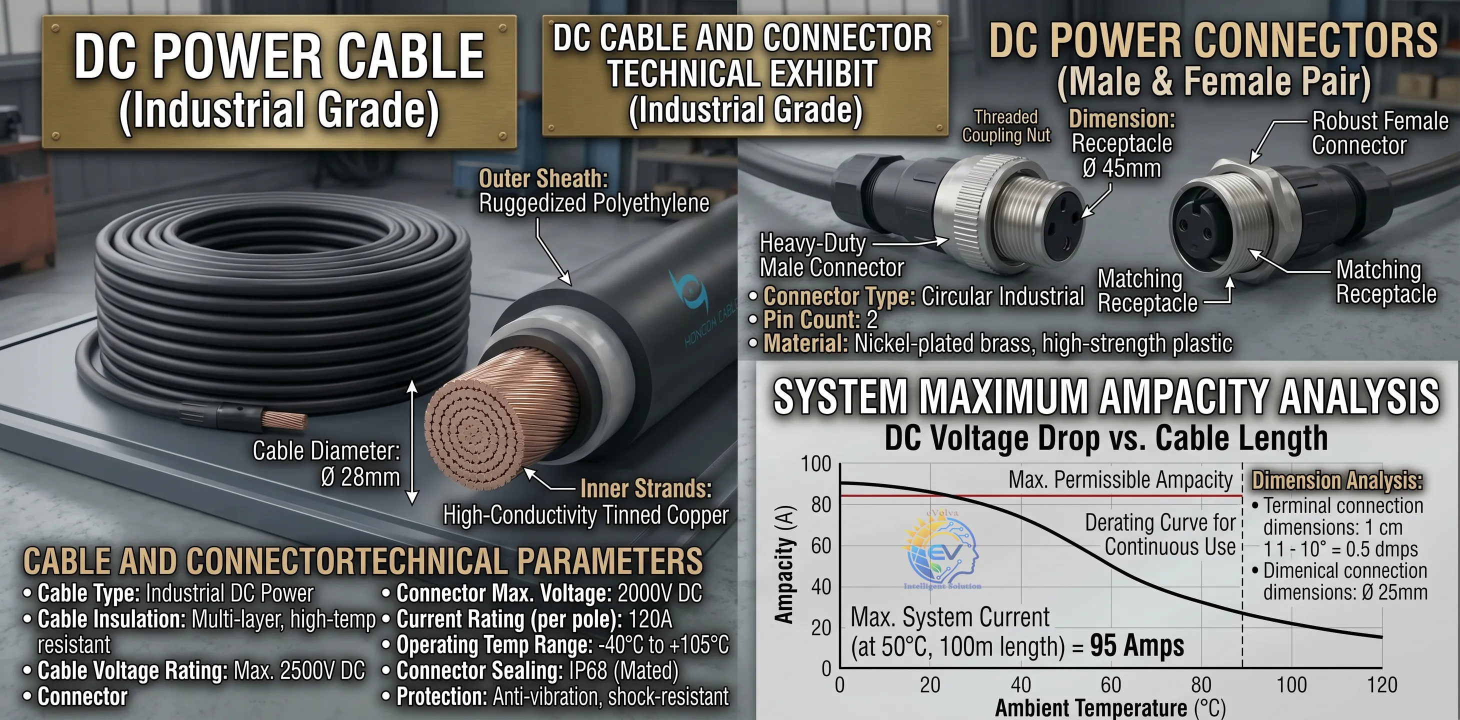
Cable and connector illustration. Printed ratings and chart labels in this image are illustrative; use the verified product datasheet for selection.
What to check on a PV cable datasheet
Parameter
What to verify
DC voltage rating
The cable rating must suit the system's maximum calculated DC voltage, including the cold-weather open-circuit voltage of the string. Common system classes include 1,000 V and 1,500 V DC.
Conductor
Confirm copper or other specified conductor material, strand class, cross-section and maximum DC resistance. Tinned copper is common in PV cable products, but verify the actual cable construction.
Insulation and sheath
Confirm the cable is designed for PV DC service and check its declared materials, temperature range, UV/weathering and moisture performance. XLPO, XLPE and other cross-linked constructions may be used, depending on the product standard.
Temperature rating
Read the continuous conductor temperature and any short-duration or cumulative high-temperature limit separately. Do not treat a limited-duration value as a normal continuous rating.
Environmental performance
Check the applicable standard's tests and the manufacturer's declarations for UV, ozone, damp heat, low-temperature handling and chemical exposure where relevant.
Product marking
Confirm standard, voltage class, conductor size, manufacturer, batch/traceability information and the cable's intended use.
IEC 62930 covers PV DC cables rated up to 1.5 kV DC. It specifies a normal continuous maximum conductor temperature of 90°C; use at 120°C is limited to a stated duration of 20,000 hours. Treat those as standard conditions, not as permission to run a cable continuously at 120°C. IEC 62930 overview
Cable ranges, sheath materials, test methods and advertised lifetimes vary by product. A listed size range such as 2.5–70 mm² is not universal, and a 25- or 30-year service-life statement should be checked against the product documentation and project conditions.
Cable sizing: select each circuit separately
Design check
Practical question
Current
What is the maximum design current for this circuit, based on module data, parallel strings and the applicable design rules?
Voltage
What is the maximum string open-circuit voltage at the lowest expected module temperature, and does the cable rating cover it?
Ampacity
Does the cable carry the design current after applying the manufacturer's correction factors for ambient temperature, rooftop temperature, grouping, conduit, tray and number of loaded conductors?
Voltage drop
Is the drop acceptable at the expected operating current and the conductor's operating temperature?
Installation
Is the cable protected from abrasion, sharp edges, standing water, rodents, direct sunlight where not rated for it, and mechanical strain at connectors?
Protection and interfaces
Are overcurrent protection, isolators, terminals, glands and connectors rated for the DC voltage and current and compatible with the cable?
Ampacity is installation-dependent
There is no single ampacity table that applies to every PV cable. A rating measured in free air at 30°C cannot be copied directly to a hot roof, a grouped cable bundle or a conduit. Use the current-carrying table for the exact cable construction and installation method, then apply all relevant correction factors. The final ampacity must also coordinate with the circuit's protective devices and equipment terminals.
Common PV cable sizes and indicative current capacity
The table below reproduces published ratings for one specific H1Z2Z2-K PV cable range. Its reference conditions are 60°C ambient temperature and a 120°C conductor temperature: one cable in air, one cable on a surface, or two cables touching on a surface. These values are useful for comparing sizes, but they are not universal ampacities and should not be copied as the design current for another cable or installation. The 120°C operating condition is limited to 20,000 hours under IEC 62930; many designs must use the manufacturer's 90°C continuous rating and applicable installation correction factors. Check the exact product datasheet and local rules before selecting a size. Nexans NPE SUN H1Z2Z2-K ratings · IEC 62930 temperature limits
PV cable cross-section
Common use (illustrative only)
One cable in air (A)
One cable on surface (A)
Two touching on surface (A)
2.5 mm²
Short, low-current string connections where allowed by the design, connector rating and equipment instructions
41
39
33
4 mm²
Common starting point for individual PV string wiring
55
52
44
6 mm²
Longer string routes or where voltage-drop calculations call for more copper
70
67
57
10 mm²
Small string-collection or DC feeder sections
98
93
79
16 mm²
Higher-current collection or feeder sections
132
125
107
25 mm²
DC trunk or feeder runs with higher current or longer route length
176
167
142
35 mm²
Higher-current DC trunk runs
218
207
176
50 mm²
Higher-current DC trunk runs
276
262
221
70 mm²
Large DC feeders where the design calculations require it
347
330
278
For many residential string circuits, 4 mm² and 6 mm² are common catalog sizes. Larger cross-sections are used where combined string current, route length, voltage drop, installation conditions or equipment terminals warrant them. A larger system does not automatically need a larger cable: calculate each circuit separately. The use descriptions above are starting points, not rules.
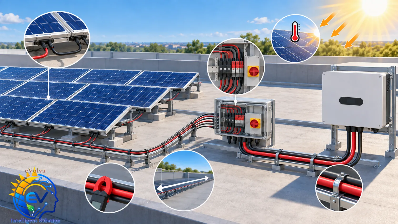
Measure the actual route and assess current, rooftop temperature and support before calculating voltage drop.
Calculate DC voltage drop
For a two-conductor DC circuit, use:
Voltage drop (V) = 2 × current (A) × one-way length (m) × conductor resistance (Ω/m)
The factor 2 includes the outgoing and return conductors. Use resistance per metre for one conductor, not the loop resistance. For multiple sections or different conductor sizes, calculate each section and add the drops.
Example: A manufacturer lists a maximum DC conductor resistance of 5.09 Ω/km at 20°C for one 4 mm² H1Z2Z2-K PV cable. For a 10 A circuit with a 30 m one-way route:
Using the 20°C resistance: drop = 2 × 10 × 30 × 0.00509 = 3.05 V.
At 500 V string operating voltage, this is about 0.61%.
This is an illustration, not a cable selection approval. It uses the cable's 20°C resistance and therefore understates voltage drop when the conductor is hotter. For final design, use the selected product's resistance at the expected operating temperature, or apply the appropriate temperature correction, and recheck the voltage drop at the circuit's expected operating current.
Reference conductor resistance
The following are reference 20°C values for plain copper conductors. The maximum resistance of the actual cable depends on conductor class and construction; use the cable manufacturer's published value for final calculations. IEC 60228 specifies conductor sizes and resistance requirements. IEC 60228 overview
Cross-section (mm²)
Reference resistance at 20°C (Ω/km)
2.5
7.41
4
4.61
6
3.08
10
1.83
16
1.15
25
0.727
35
0.524
50
0.387
70
0.268
Set a project voltage-drop target
These can be used as starting design goals, not as universal regulatory limits. Confirm the target against local rules, the inverter's MPPT voltage range, array layout and the project's energy-loss budget.
Application
Illustrative project target
Residential PV string
≤ 1%
Commercial rooftop PV string
≤ 1.5%
Combiner-box DC trunk
≤ 2%
Utility-plant DC trunk
≤ 2%
Standards and local compliance
Choose a cable certified to the PV cable standard required in the project jurisdiction. For Indian projects, BIS lists IS 17293:2020 as the standard for electric cables for photovoltaic systems rated at 1,500 V DC. IS 17048:2018 is the Indian standard for halogen-free flame-retardant cables for working voltages up to 1,100 V; it is not the dedicated PV cable standard. Check the current product quality-control requirements and the latest applicable CEA safety regulations and amendments before procurement. BIS listing for IS 17293 · BIS product manual for IS 17048 · CEA safety regulations and amendments
For projects in Myanmar or another jurisdiction, verify the local electrical rules, utility requirements and project specifications. Indian BIS and CEA requirements apply only where the project or contract makes them applicable.
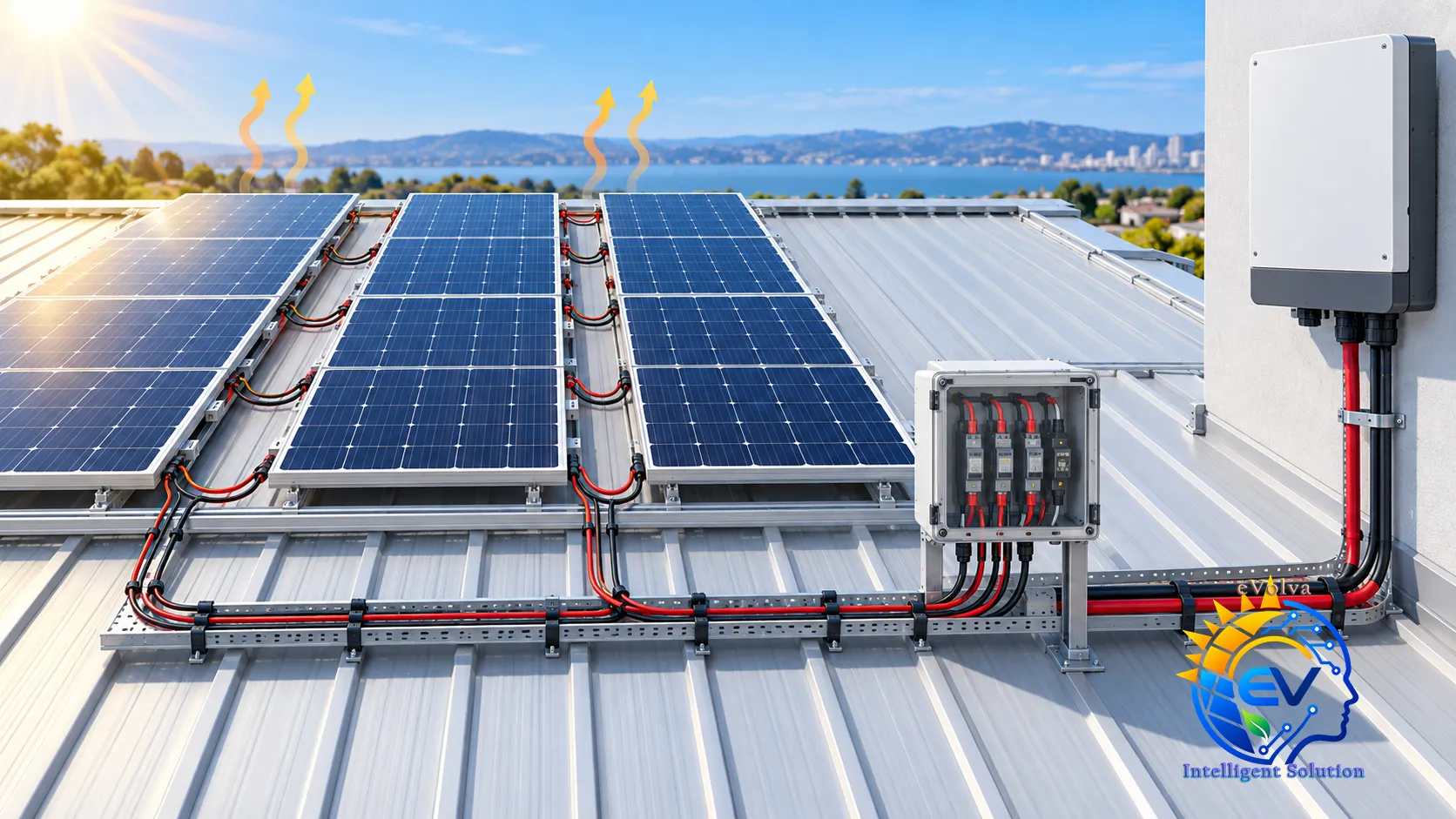
Route and support the positive and negative conductors together; check connectors, cable entries and exposure.
Good installation practice
Keep positive and negative conductors routed together where practical, with secure support and suitable mechanical protection.
Keep cables away from sharp sheet-metal edges, hot surfaces and standing water. Use UV-rated cable ties or supports outdoors.
Do not leave connectors resting on a roof or under mechanical tension. Use the specified crimp tool, contacts and strip length.
Mate connectors only when the manufacturers identify them as compatible. Similar-looking “MC4-style” connectors are not automatically interchangeable.
Never unplug a PV connector under load unless the connector and approved procedure are specifically rated for that operation. Isolate and verify safely before maintenance.
Inspect cable entries, terminations, bends and connector housings during commissioning and maintenance. Look for cuts, crushing, discoloration, looseness or water ingress.
PV modules can produce voltage in daylight. Follow the inverter and equipment manuals and the site's electrical safe-work procedure during installation, testing and service.
Where PV DC cables are used
Residential rooftop strings
Commercial and industrial rooftop arrays
Combiner-box to inverter DC trunk runs
Ground-mounted string runs, coordinated with the array layout
Charge-controller PV inputs
Solar canopies and other PV structures
Frequently asked questions
Does a larger solar system always need a larger PV cable?
No. System kWp alone is not enough to select a cable. The result depends on circuit current, string voltage, one-way route length, installation conditions, voltage-drop allowance and applicable requirements.
Is the protective-earth (PE) wire sized from the PV string current?
No. PE and bonding conductors are selected separately under the applicable electrical rules, equipment instructions and fault-protection design. They are not the normal current-return path for the PV string. See the solar inverter grounding safety guide.
Can I use ordinary building wire for the PV array?
Only if the cable is explicitly permitted by the applicable rules and its voltage, temperature, outdoor, UV and mechanical ratings match the installation. A cable that merely has an adequate cross-section may still be unsuitable for exposed PV DC service.
Final design check
Before ordering cable, confirm the maximum cold-weather string voltage, design current, cable ampacity after derating, hot-conductor voltage drop, route protection, connector compatibility, overcurrent coordination and local compliance. Record the selected cable type and size for each circuit on the drawings and installation schedule.
*This article is general design guidance. Final cable selection and installation should be checked by a qualified electrical designer against the project conditions, current local requirements and equipment manufacturers' instructions.*
ဗဟုသုတ · PV String DC
ဆိုလာ PV DC ကေဘယ်ရွေးချယ်ခြင်း — အရွယ်အစား၊ ဗို့အားကျဆင်းမှုနှင့် လုံခြုံရေး
အအေးဆုံးအချိန် string ၏ ဝန်မချိတ်ထားသောဗို့အား (Voc) အပါအဝင် တွက်ချက်ထားသည့် အများဆုံး DC ဗို့အားနှင့် ကိုက်ညီရမည်။ အသုံးများသော စနစ်ဗို့အားအမျိုးအစားများမှာ 1,000 V နှင့် 1,500 V DC ဖြစ်သည်။
စီမံကိန်းတည်နေရာတွင် လိုအပ်သော PV ကေဘယ်စံနှုန်းအတိုင်း အသိအမှတ်ပြုထားသော ကေဘယ်ကို ရွေးပါ။ အိန္ဒိယစီမံကိန်းများအတွက် BIS က IS 17293:2020 ကို 1,500 V DC photovoltaic စနစ်ကေဘယ်စံအဖြစ် ဖော်ပြထားသည်။ IS 17048:2018 သည် လည်ပတ်ဗို့အား 1,100 V အထိ halogen-free မီးပြန့်နှံ့မှုနှောင့်နှေးစေသော ကေဘယ်စံဖြစ်ပြီး သီးသန့် PV ကေဘယ်စံ မဟုတ်ပါ။ ဝယ်ယူမီ လက်ရှိ product အရည်အသွေးထိန်းချုပ်မှုလိုအပ်ချက်နှင့် နောက်ဆုံးသက်ဆိုင်ရာ CEA လုံခြုံရေးစည်းမျဉ်း/ပြင်ဆင်ချက်များကို စစ်ဆေးပါ။ BIS IS 17293 စာရင်း · BIS IS 17048 product လက်စွဲ · CEA လုံခြုံရေးစည်းမျဉ်းနှင့် ပြင်ဆင်ချက်များ