Concept illustration; follow the exact product installation instructions.
From sunlight to DC power
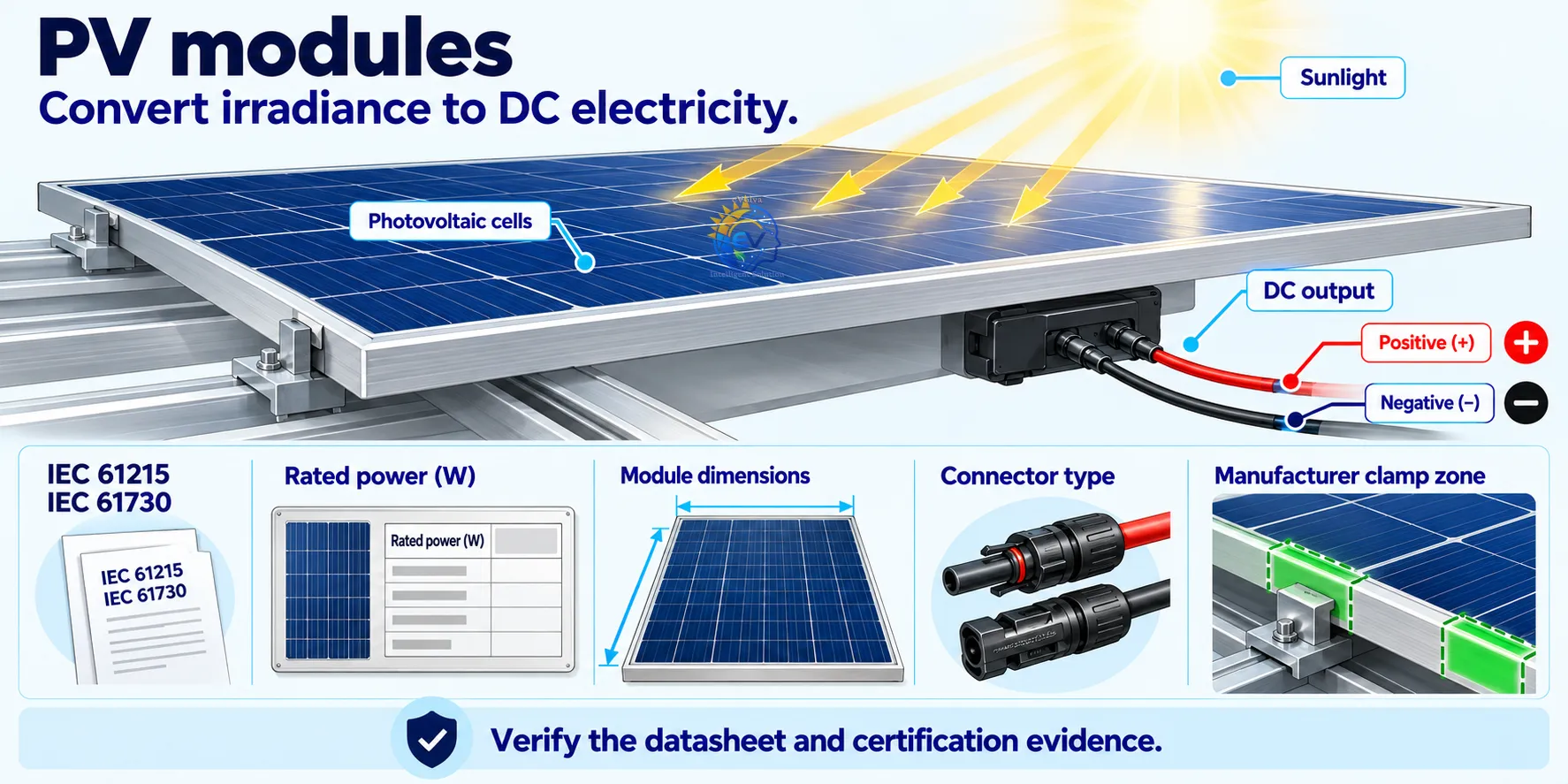
Photovoltaic cells convert sunlight into DC electricity. Module power is rated under specified test conditions; actual output changes with irradiance, cell temperature and shading. Read Pmax, Voc, Vmp, Isc and Imp before designing strings.
Check certification and fit
Check IEC 61215 design-qualification evidence and IEC 61730 safety-qualification evidence for the exact module model. Certification does not replace a site design or guarantee a particular energy yield. Confirm dimensions, weight, approved clamp zones, mechanical load limits and connector manufacturer/model in the installation manual.
Before mounting
Inspect glass, frame, junction box and leads for damage. Plan compatible strings, cold-weather Voc and inverter MPPT current. Record serial numbers and retain the datasheet and installation manual.
Concept illustration; follow the exact product installation instructions.
A continuous load path
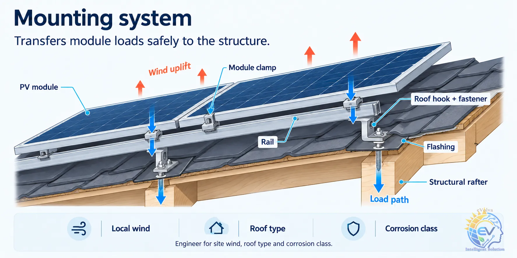
Mounting hardware transfers module weight and wind forces through clamps, rails, roof attachments and fasteners into the supporting structure. The roof covering alone is not the structural load path. Roof hooks in the image illustrate one roof type; other roofs need their approved attachment systems.
Design for the site
Assess roof condition, structural capacity, local wind, exposure, array edge zones, roof type and corrosion environment. Use the mounting manufacturer’s engineering limits for attachment spacing, rail spans and cantilevers, together with the module’s clamp zones. A structural designer must resolve conditions outside those limits.
Install and inspect
Use specified flashing and waterproofing details, compatible fasteners and manufacturer torque values. Preserve drainage, access and required clearances. Inspect attachment engagement, rail alignment and clamp position; document the installed layout.
Concept illustration; follow the exact product installation instructions.
Select for outdoor PV service
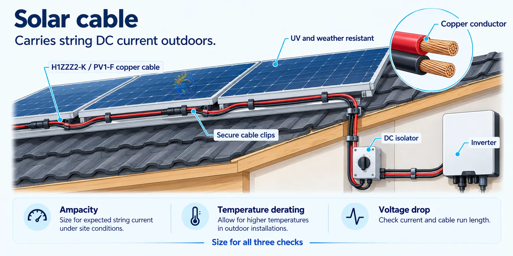
Use cable explicitly rated for the required PV DC voltage, conductor temperature and outdoor environment. Verify the exact product marking and datasheet rather than assuming every H1Z2Z2-K or PV1-F product has identical ratings.
Pass all sizing checks
Calculate circuit design current, cold-weather maximum string voltage and voltage drop over both positive and negative conductors. Apply temperature, grouping and installation correction factors to ampacity. Connector and inverter terminal limits must also be satisfied.
Support the route
Route positive and negative together where practical. Use outdoor-rated supports; keep cables and connectors clear of sharp edges, roof contact and standing water. Allow the specified bend radius and strain relief. Record polarity and string Voc before connection.
Concept illustration; follow the exact product installation instructions.
Use a matched connector pair
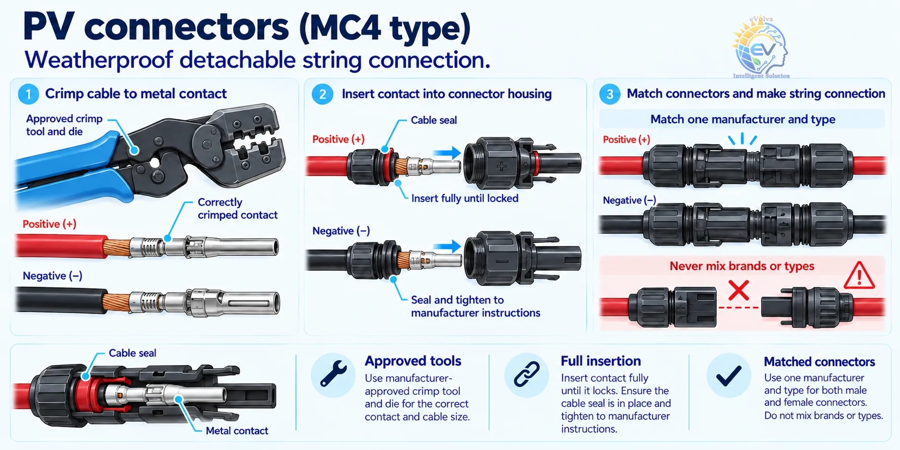
Use the specified manufacturer and compatible product family for each mating pair. Similar appearance or an “MC4-compatible” label does not establish approved compatibility. Confirm cable cross-section, outside diameter, voltage and current limits for the exact connector.
Assemble to the manual
Use the approved contact, stripping length, crimp tool and die. Fully seat the contact, fit the cable seal and tighten the gland to the specified procedure. Verify locking and inspect the crimp. Connector housing gender does not establish electrical polarity: verify the circuit markings and test polarity.
Keep connections safe
Do not disconnect under load. Follow the equipment isolation procedure; modules may remain energized in daylight. Keep mating surfaces clean and dry, use approved caps for unmated connectors and support connections away from roof surfaces and mechanical tension.
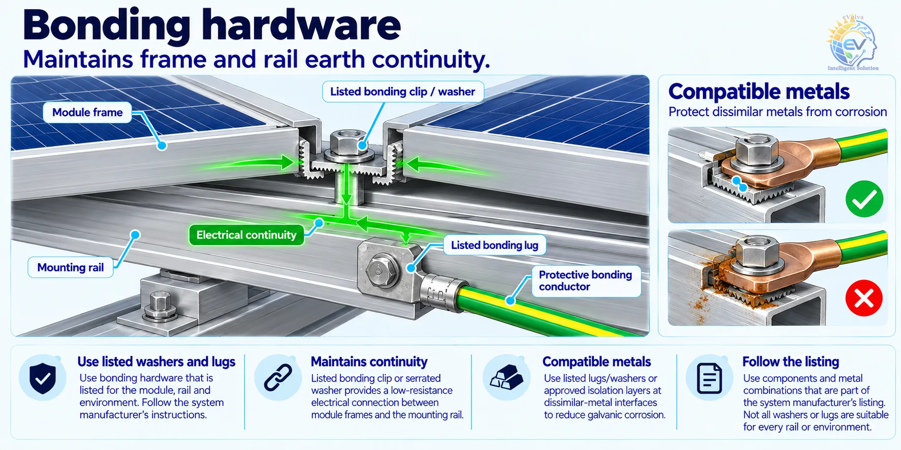
Concept illustration; follow the exact product installation instructions.
Maintain the protective path
Approved bonding clips, washers and lugs create the specified electrical path between module frames and mounting rails. Use components evaluated for the exact module, rail and environment; a random bolt or incidental metal contact is not a verified bonding connection.
Control corrosion and continuity
Follow the system’s permitted metal combinations, coating treatment and installation torque. Use approved corrosion-control details at dissimilar-metal interfaces without interrupting the intended bonding path. Check rail splices and removable sections; fit bonding jumpers only where the approved design requires them.
Test and document
Identify the connection to the protective earthing system and select the conductor from the protection design and local rules. Verify continuity with an appropriate test method, inspect hardware and label the documented path. Recheck affected connections after module replacement.