Match the mounting system to the roof or ground structure, module frame and site conditions. Plan the complete assembly before ordering.
1. Rails, splices & end caps
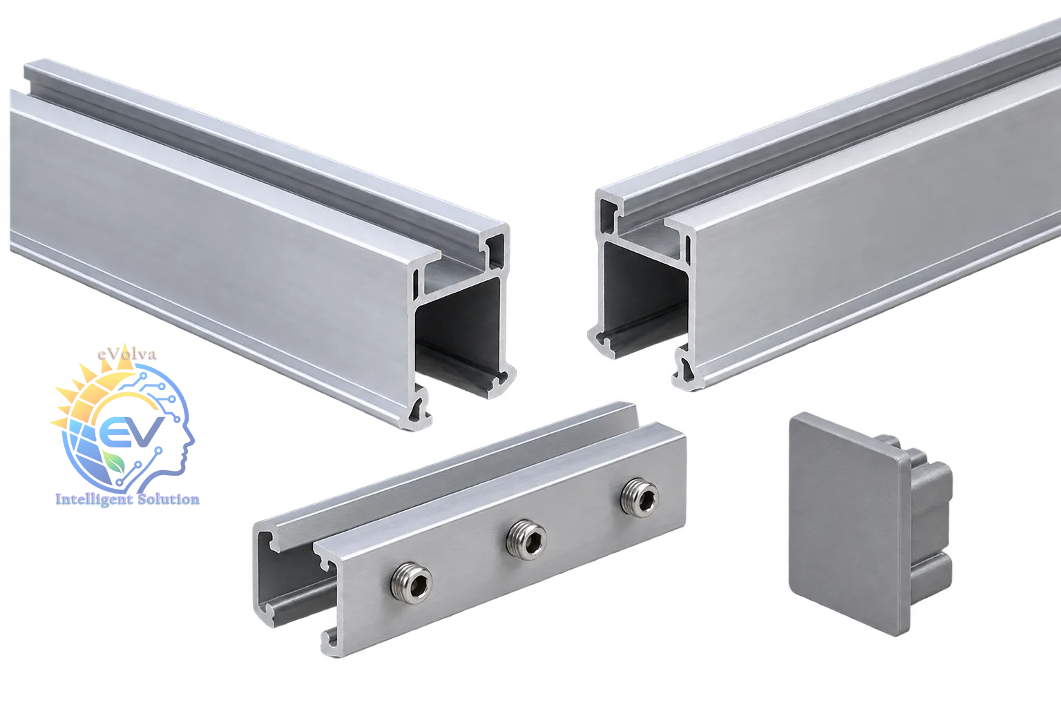
Select rails, splices, fasteners and end caps from a compatible mounting system. Check the rail profile and the approved connection details before ordering.
Accessory set — Rails, splices & end caps
Selection checks
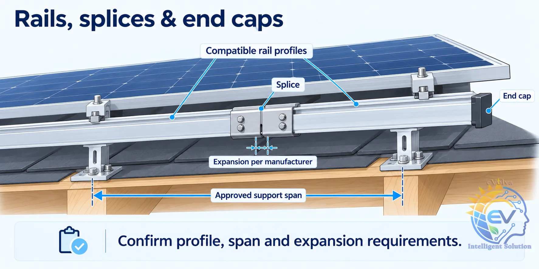
Use the manufacturer’s engineering tables for support spacing, cantilever and site loads. A splice location can affect the permitted span; do not assume every joint transfers loads in the same way.
Selection and installation illustration — Rails, splices & end caps
Installation and final checks
Allow thermal movement using the specified expansion joints and gaps. Tighten splice fasteners to the product instructions and verify whether the splice provides the required bonding path. End caps finish the rail; they do not replace a structural connection.
Planning the complete rail assembly
Confirm the required rail lengths and quantities from the module layout, including row ends and joints. Keep a parts list for each rail profile so that splice kits, bolts and caps are ordered together. Record the approved support locations on the installation drawing.
For inspection, compare the installed joints and expansion breaks with the manufacturer’s layout requirements. Check for damaged profiles, missing fasteners and unsupported joints. Keep the product model and manual revision in the project records.
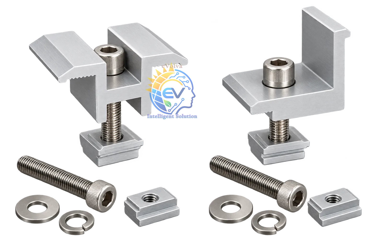
Match clamp height to the module frame thickness and confirm compatibility with the rail and module model. Mid clamps hold adjoining modules; end clamps secure the outer edge.
Accessory set — Mid & end clamps
Selection checks
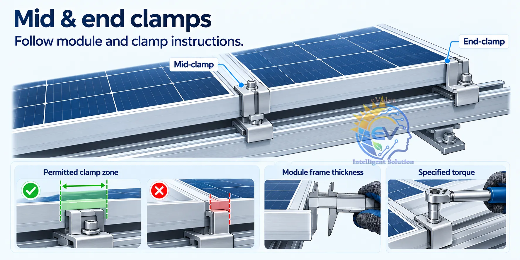
Position clamps only in the module manufacturer’s permitted zones. Check orientation, clamp length and engagement, together with the mounting system’s load limits.
Selection and installation illustration — Mid & end clamps
Installation and final checks
Use the specified fastener and tightening torque with an appropriate torque tool. There is no universal torque for all clamps. Inspect frame engagement and spacing; use a clamp as a bonding connection only when that function is approved.
Ordering and checking the clamp set
Count the mid clamps at shared module edges and end clamps at the outside ends of each row. Confirm the exact kit contents, including bolts and rail nuts. A clamp that appears to fit may still fall outside the approved frame-height range.
Before tightening, align modules and seat the clamp correctly on the frame. Avoid loading the glass or trapping cables beneath the clamp. After tightening, inspect every clamp and record the specified torque used; follow the manual if it requires a later inspection.
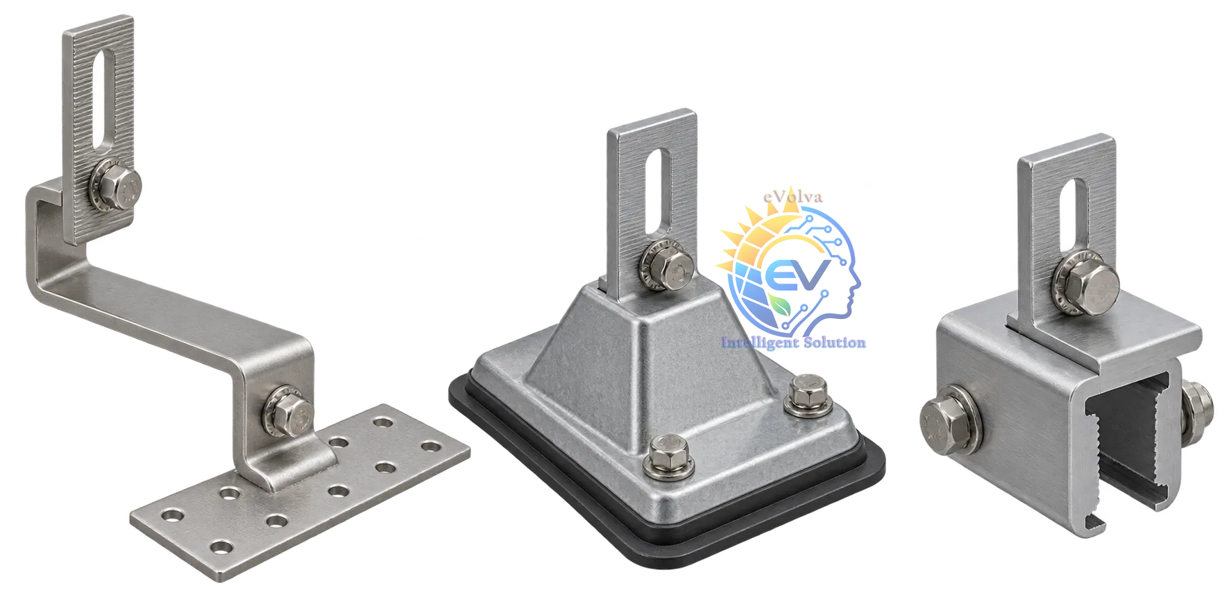
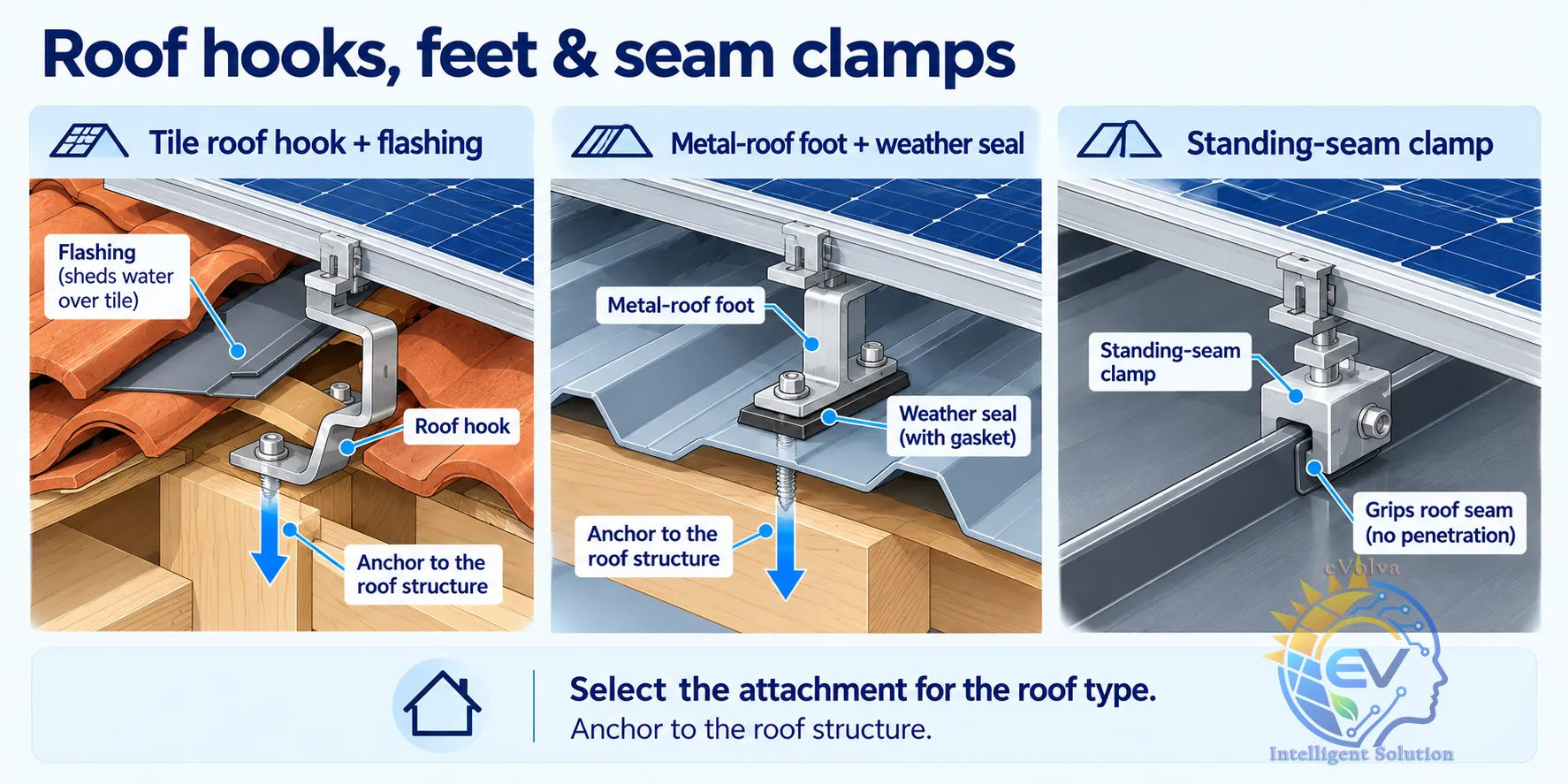
Choose attachments for the actual roof covering and supporting structure. Tile hooks, metal-roof feet and standing-seam clamps have different installation requirements.
Accessory set — Roof hooks, feet & seam clamps
Selection checks
Anchor penetrating attachments to the specified structural member with approved fasteners and embedment. Use the designed flashing, gasket or weather seal and preserve the roof’s drainage path.
For standing-seam roofs, confirm the exact seam profile, roof material and tested clamp model. Follow the specified setscrew procedure and load ratings. Check roof condition, corrosion compatibility and waterproofing after installation.
Survey the roof before selecting attachments
Identify the roof covering, supporting members, seam dimensions and any existing damage. Confirm that the attachment transfers load into the intended structure. Plan attachment positions together with rail spans, roof edges and access routes.
Coordinate penetrations and seals with the roof manufacturer’s instructions. Do not substitute a generic sealant for a specified flashing system. For seam clamps, verify the tested roof-and-clamp combination and check that installation does not deform or damage the seam.
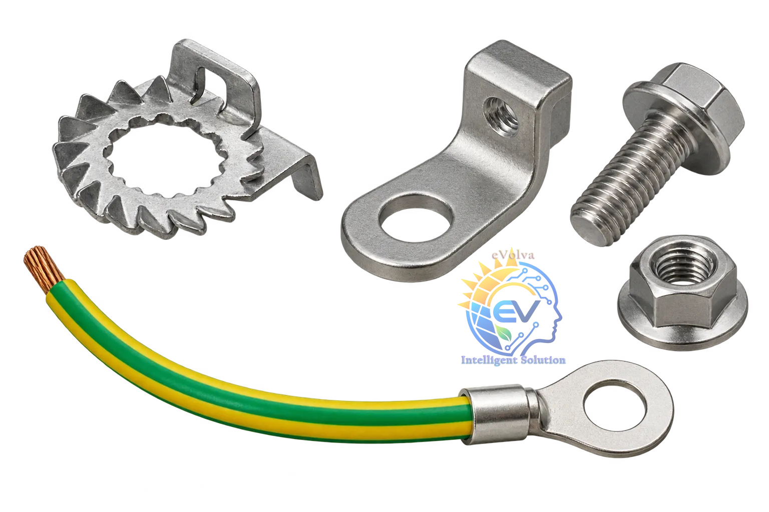
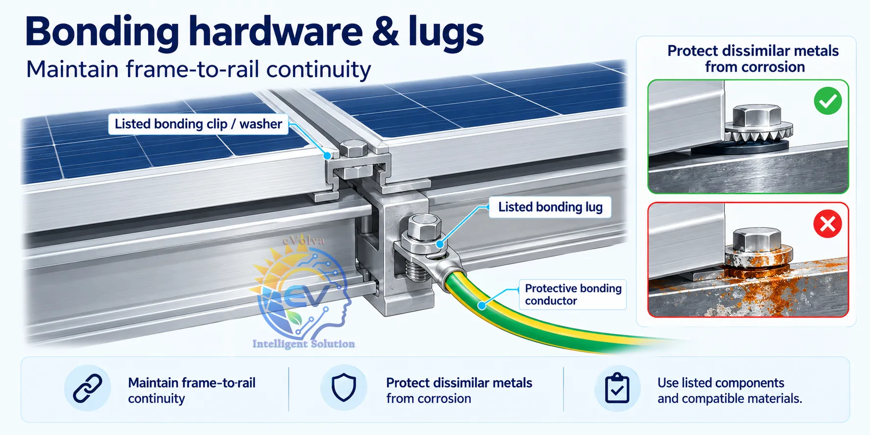
Use bonding clips, washers and lugs approved for the exact module frame, rail and environment. The assembly must maintain the designed protective electrical path.
Accessory set — Bonding hardware & lugs
Selection checks
Follow instructions for contact surfaces, conductor size, fasteners and torque. Protect dissimilar metals with approved materials without interrupting the intended electrical connection. An ordinary washer is not automatically a bonding washer.
Selection and installation illustration — Bonding hardware & lugs
Installation and final checks
Check continuity across rails, splices and removable sections using the required test procedure. Record the bonding route and restore affected connections after module replacement. Select the protective conductor using the PE design requirements.
Document the protective connection
Show the intended frame-to-rail and rail-to-earth connections on the drawing. Check whether each splice and clamp is part of the approved bonding path or whether a specified jumper is required. Keep conductor and lug compatibility information with the equipment schedule.
Installation order matters when bonding washers or clips must pierce a coating. Follow the approved assembly sequence and replacement rules. After disturbing a connection, inspect and test the affected path again before returning the system to service.
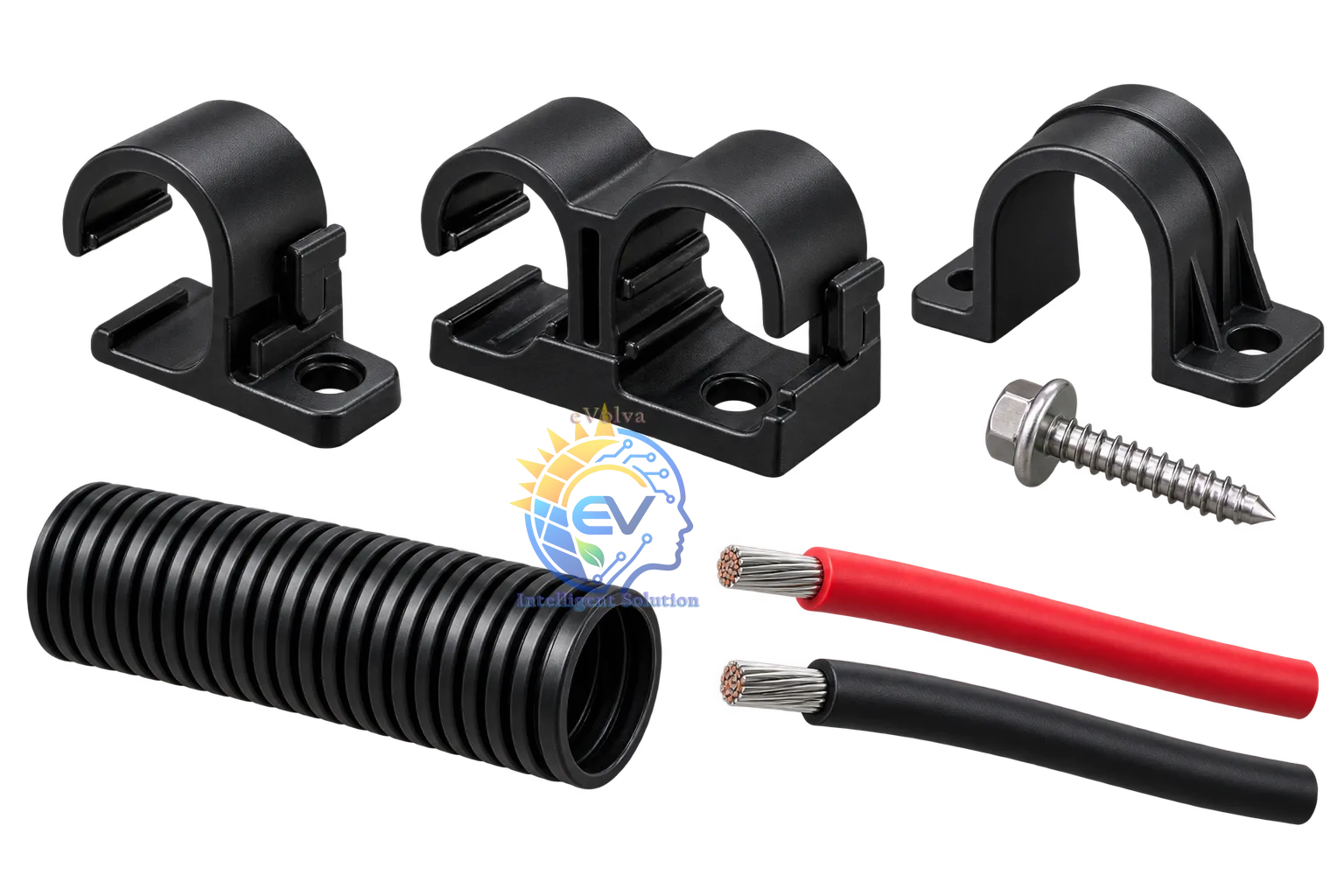
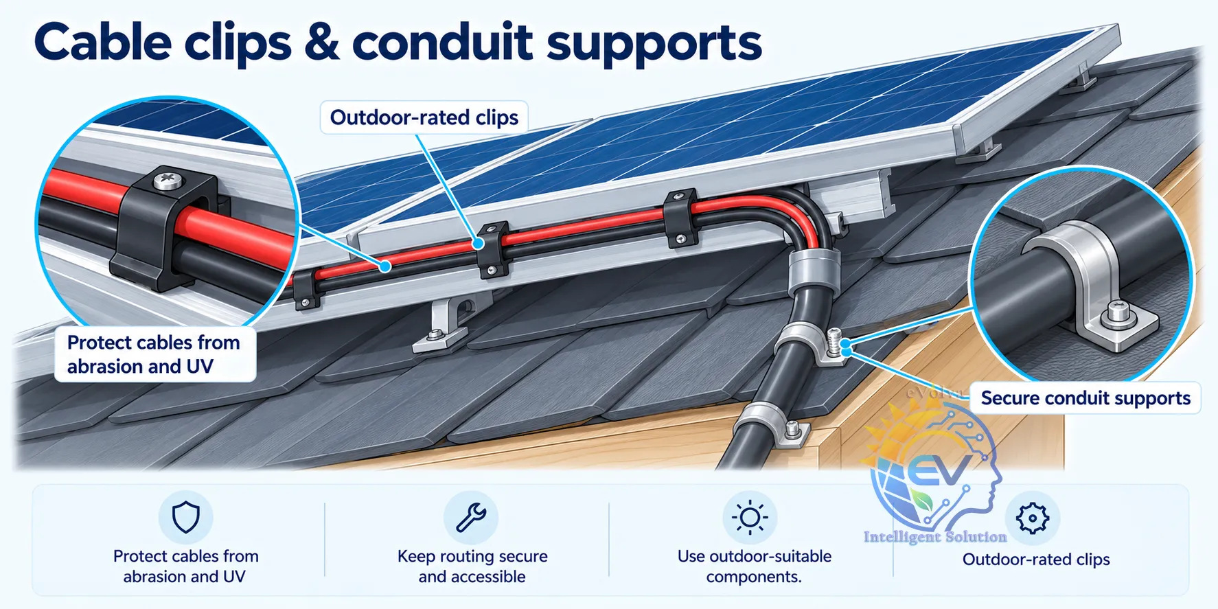
Select outdoor components suitable for UV exposure, temperature, moisture and the actual cable or conduit diameter. Check material compatibility with the mounting structure.
Accessory set — Cable clips & conduit supports
Selection checks
Keep cables clear of sharp edges, moving parts, roof surfaces and standing water. Follow the cable’s bend radius and provide strain relief at connectors. Support spacing must follow the relevant product instructions.
Selection and installation illustration — Cable clips & conduit supports
Installation and final checks
Secure conduit without crushing it and protect entry points with appropriate fittings. Keep routes accessible for inspection and replacement. Check clips and supports for looseness, corrosion and cable abrasion during maintenance.
Plan supports with the cable route
Mark clips, conduit supports and transitions on the routing plan. Allow for connector access and cable movement without placing tension on connections. Select supports by the cable count and diameter, and account for any installation derating caused by grouping or enclosure.
Inspect the completed route from the modules to the equipment entry. Check that connector bodies are supported, conduit ends do not abrade insulation and water cannot collect in vulnerable locations. Replace deteriorated clips with components suitable for the same outdoor conditions.
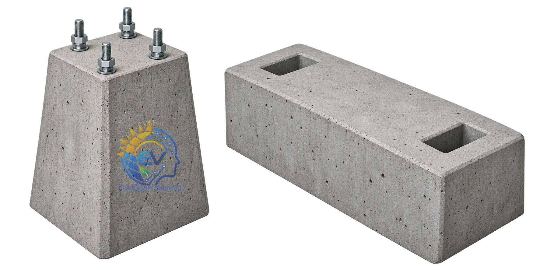
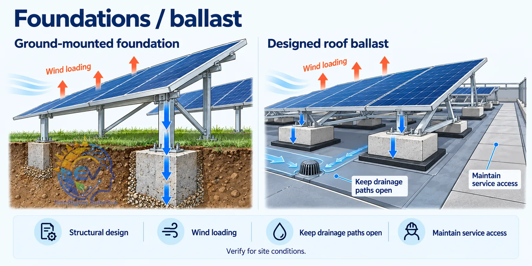
Match the foundation or ballast system to the site’s structural design and wind loads. Ground foundations depend on soil conditions; roof ballast depends on roof capacity and the mounting layout.
Accessory set — Foundations / ballast
Selection checks
Use the approved foundation dimensions, anchors or ballast schedule. Check uplift, sliding and overturning as required by the design. A pictured concrete block does not establish the required weight or footing depth.
Selection and installation illustration — Foundations / ballast
Installation and final checks
Preserve drainage and maintenance access. On roofs, use specified membrane protection and confirm compatibility with the roof covering. Inspect alignment, anchor connections and block placement against the final engineered plan.
Prepare the site and verify the layout
Confirm soil or roof information before finalizing the foundation design. Mark the proposed locations and check for buried services, roof drains and maintenance routes. Keep the engineered foundation or ballast schedule with the installation drawings.
Verify installed dimensions, anchor positions and ballast distribution against the approved plan. A heavier block does not automatically resolve sliding, roof loading or overturning. Record any site changes and have their structural effect reviewed before changing the designed arrangement.