Knowledge base · Inverter AC Cable
Inverter AC Cable Selection: Phase, Current, Voltage Drop and Fault Withstand
Why inverter AC cable selection matters
The cable between an inverter and the switchboard, grid connection or backed-up load panel carries the inverter's AC output. Selecting it means more than matching the cable to the inverter's kilowatt rating. The circuit must have the right number of conductors, carry the inverter's maximum continuous current after installation derating, keep voltage drop or export voltage rise within design limits, fit the terminals and withstand the fault conditions until protection operates.
The grid connection and the inverter's backup or EPS output may be separate circuits. On a hybrid inverter, check each port independently: phase count, neutral arrangement, rated current, overload behavior, protective-device requirements and terminal limits may differ.
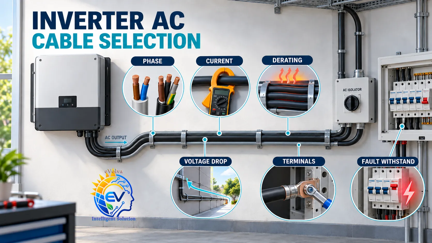
Start with phase arrangement and the circuit diagram
Confirm the actual supply and inverter configuration before selecting cable cores. Common low-voltage arrangements include single-phase circuits and three-phase circuits, but the inverter manual and local supply arrangement govern the design.
| Circuit arrangement | Conductors commonly considered | What to verify |
|---|---|---|
| Single-phase | Line (L), neutral (N) where required, and protective earth (PE) | Confirm the inverter's line-neutral or line-line output, neutral requirements, and backup transfer arrangement. |
| Three-phase, three-wire | L1, L2, L3, and PE | Confirm the inverter supports this exact arrangement and whether it requires a neutral connection. |
| Three-phase, four-wire | L1, L2, L3, N, and PE | Confirm neutral current requirements, including any harmonic effects, and the inverter's neutral and bonding instructions. |
Do not infer the cable core count from the number of inverter terminals alone. Some inverters have separate grid and backup terminals; some require a neutral, while others do not. Follow the manufacturer's wiring diagram. Size the PE conductor separately under the applicable protective-conductor rules; it is not a normal current-carrying return conductor.
Use the inverter's continuous AC current
The preferred starting point is the inverter datasheet's maximum continuous AC output current for the selected phase arrangement and port. Use the grid-port rating for the grid connection and the EPS/backup rating for the backup circuit. Do not size from kW alone where the inverter's current limit, power factor, operating voltage or overload rating produces a different result.
If the current is not stated, an approximate balanced-load calculation is:
- Single-phase:
I ≈ P ÷ (V × PF) - Three-phase:
I ≈ P ÷ (√3 × VLL × PF)
Here, P is real power in watts, V is the single-phase circuit voltage, VLL is the three-phase line-to-line voltage, and PF is power factor. If the rating is stated in apparent power S (VA), use I = S/V for single-phase or I = S/(√3 × VLL) for balanced three-phase.
Example: same power, different phase arrangements
For an illustrative 5 kW inverter at power factor 1:
| Example output | Approximate line current |
|---|---|
| 230 V single-phase | 21.7 A |
| 400 V three-phase | 7.2 A per line |
These are arithmetic examples at nominal voltage, not cable or breaker selections. Use the inverter's published maximum current and the actual voltage and phase arrangement for design.
For four-wire systems, do not reduce the neutral conductor automatically. Neutral current depends on the connected loads, phase balance, harmonics and equipment design. Follow the inverter documentation and the rules adopted for the installation.
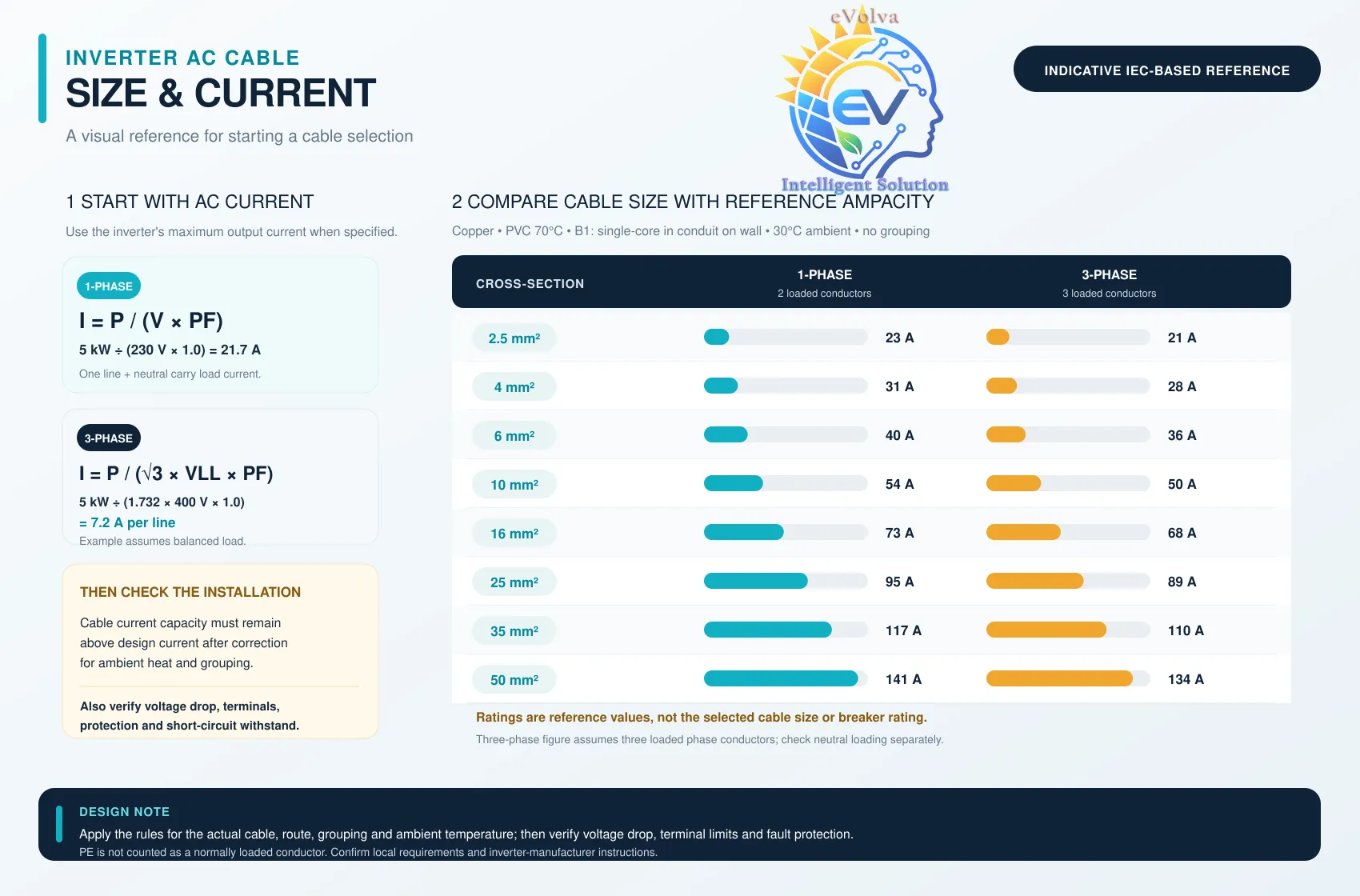
Check continuous ampacity after derating
The selected cable's allowable current must be at least the design current after applying the correction factors that match the installation. Ampacity can change with:
- Conductor material, insulation type and temperature rating
- Cable size, number of loaded conductors and single-core or multicore construction
- Installation method: clipped direct, tray, conduit, trunking, buried or enclosed
- Ambient temperature, roof temperature and proximity to hot equipment
- Grouping with other loaded circuits, thermal insulation and ventilation
- Terminal temperature ratings and any manufacturer-specific limits
Use the applicable current-carrying table for the cable construction and installation method. Apply the relevant correction factors, then coordinate the final conductor with the overcurrent protective device and the inverter's specified maximum breaker or fuse. A cable's ampacity is not a universal number that can be read from cross-section alone.
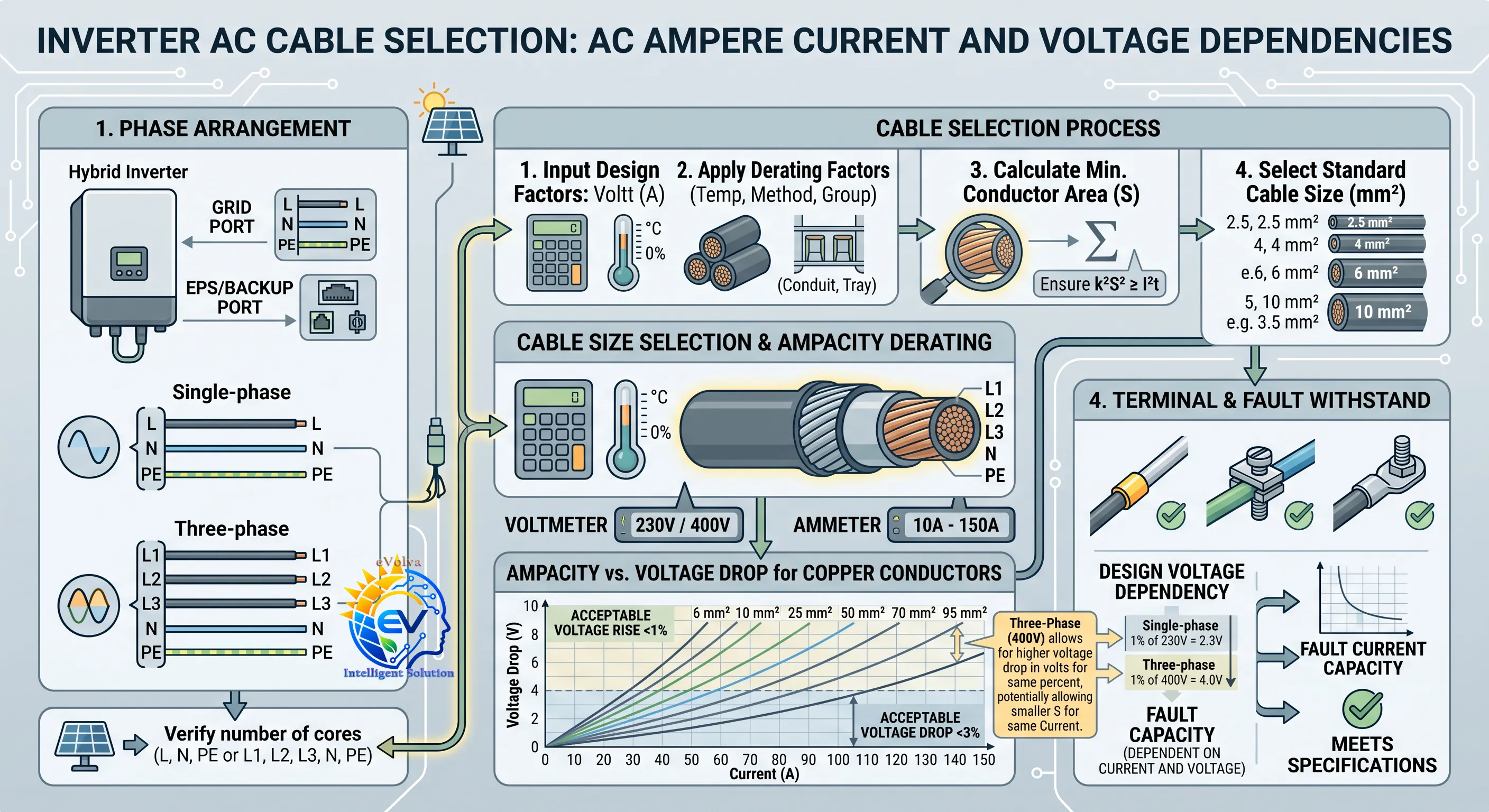
Calculate voltage drop and voltage rise
Cable impedance changes voltage between the inverter and the connection point. On a grid-connected solar inverter exporting power, the inverter pushes current toward the point of connection, so cable impedance can produce voltage rise at the inverter end. Excessive rise may cause the inverter to limit output or disconnect. On a load circuit, excessive drop can reduce voltage at equipment. Check the direction of power flow and the voltage limits that apply to the circuit.
For a balanced AC circuit, an approximate voltage-drop calculation is:
- Single-phase:
ΔV ≈ 2 × L × I × (R cosφ + X sinφ) - Three-phase:
ΔV ≈ √3 × L × I × (R cosφ + X sinφ)
Use one-way route length L in kilometres and conductor resistance R and reactance X in ohms per kilometre at the appropriate operating temperature. For short, small-cable runs, resistance may dominate; for longer or larger circuits, use the cable's impedance data. If power factor is close to 1, the reactance term is smaller. Calculate the percentage using the circuit's applicable nominal voltage: voltage change (%) = ΔV ÷ V × 100.
There is no single percentage target for every country, utility and inverter. Confirm the permitted voltage change against the local wiring rules, utility interconnection requirements, inverter operating limits and project design criteria. IEC 60364-5-52 addresses wiring-system selection and voltage-drop limits, with the adopted national rules determining the applicable project requirements. IEC 60364-5-52 consolidated edition
Match the terminals, lugs and cable construction
Before ordering cable, compare its conductor size and construction with the inverter's terminal specification. Check:
- Permitted cross-section and conductor material (copper or aluminium)
- Solid, stranded or flexible conductor class accepted by the terminal
- Whether a lug, ferrule or a specific crimp termination is required or allowed
- Lug hole size, terminal stud size, cable-entry range and bending space
- Insulation temperature rating, strip length and specified tightening torque
- Whether parallel conductors per phase are permitted and how they must be terminated
Use the manufacturer's specified lug, crimp tool, strip length and torque. Do not cut strands, force an oversized conductor into a terminal or put multiple conductors under one clamp unless the inverter documentation explicitly allows it. A conductor can be electrically large enough but mechanically incompatible with the equipment.
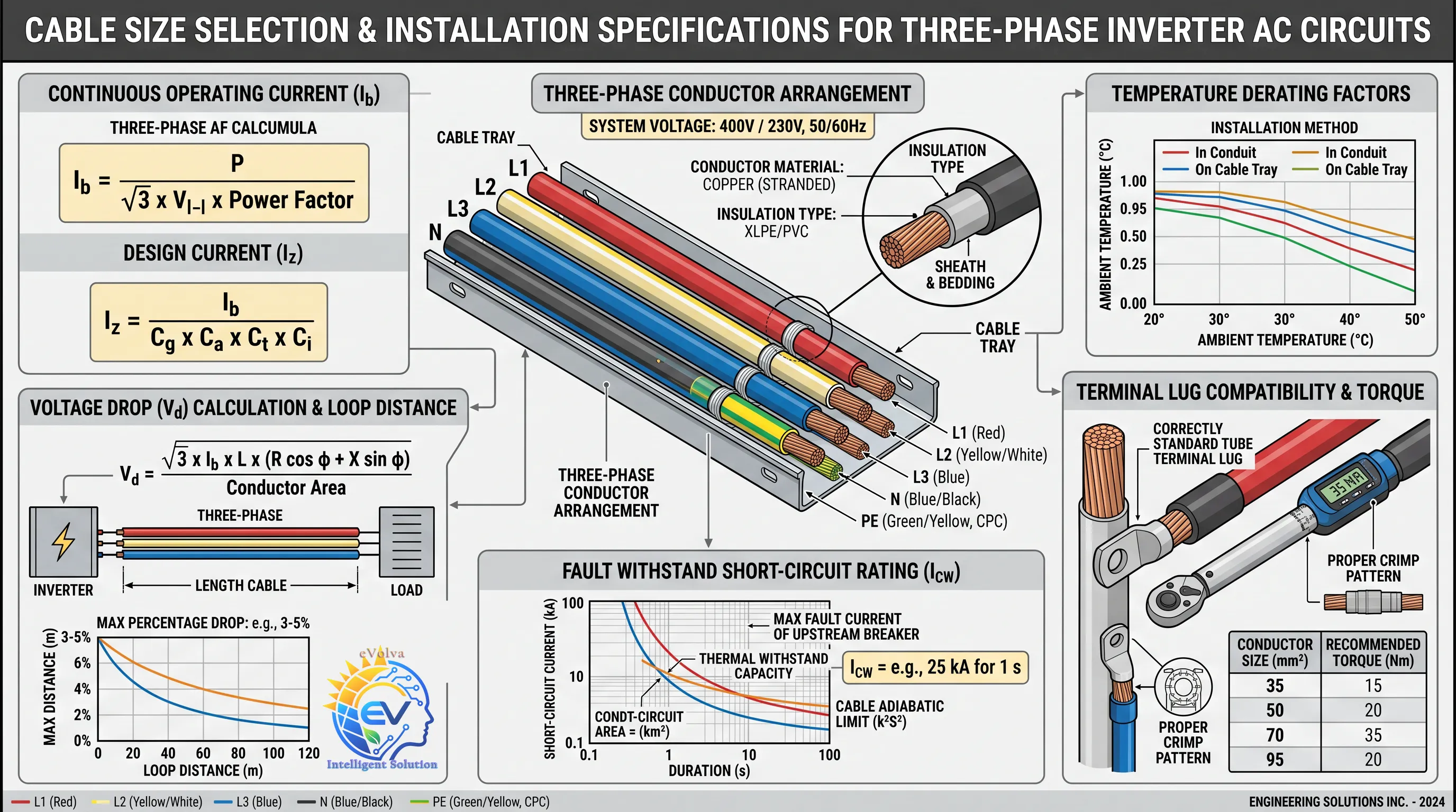
Verify overcurrent protection and fault withstand
The AC cable, breaker or fuse, inverter and supply must be coordinated. Confirm the protective device's continuous rating and trip behavior are suitable for the cable and inverter, and that its AC voltage and interrupting rating suit the installation's prospective fault current. IEC 60364-4-43 covers protection against overcurrent and coordination of overcurrent protective measures. IEC 60364-4-43:2023
Check both the utility or generator fault contribution and the inverter's limited or controlled contribution, as relevant to the operating mode. A grid-connected circuit may see substantial fault current from the supply even if the inverter limits its own contribution. Backup or islanded operation can behave differently, and a conventional breaker may not trip in the same way if the inverter current-limits a fault.
The conductor must withstand the fault energy until the protective device clears it. For short-duration thermal checks, standards use methods such as the adiabatic relationship I²t ≤ k²S², where I²t is the protective device's let-through energy, S is conductor cross-section and k depends on conductor material, insulation and permitted temperature limits. Use the applicable standard's method and manufacturer data; do not select a k value by guesswork. Also verify the protective device's breaking capacity against the maximum prospective current at its location.
Practical inverter AC cable selection sequence
- Identify whether the cable serves the grid port, a backup/EPS port or another AC output.
- Confirm the phase arrangement, nominal voltage, number of conductors, neutral requirement and PE route.
- Record the inverter's maximum continuous output current and protective-device requirements for that port.
- Select an initial conductor using the applicable ampacity table, then apply installation and temperature derating.
- Calculate voltage drop or export voltage rise over the actual route at the design current.
- Check conductor and protective-device fault withstand, interrupting rating and clearing behavior.
- Verify terminal compatibility, cable entry, bend radius, lug, crimp and tightening torque.
- Document the selected cable, protective device, route, phase arrangement and design assumptions on the electrical drawings.
Common questions
Can I use the same AC cable size for the grid and backup outputs?
Not automatically. The inverter may have different maximum current, phase configuration, neutral behavior and overload duration on the grid and backup ports. Check each output's datasheet and terminal limits.
Does a three-phase inverter always need a neutral conductor?
No. It depends on the inverter model and the connected system. Follow the wiring diagram and confirm the neutral arrangement with the designer and local rules.
Is the inverter's built-in protection enough for the AC cable?
Do not assume so. Check the required external breaker or fuse, conductor ampacity, fault current, device interrupting rating and protection behavior for each operating mode.
Is the PE conductor sized like a phase conductor?
No. PE is selected under protective-conductor and fault-clearing rules, equipment instructions and the installation's earthing arrangement. Keep it identified and connected as required; do not use it as the normal neutral return.
Final design check
Before installing, confirm the output port and phase arrangement, inverter maximum continuous current, cable ampacity after derating, voltage drop or rise, terminal and lug compatibility, overcurrent protection, prospective fault current, conductor withstand and local requirements. Record the design values so the cable can be inspected and verified during commissioning.
This article is general design guidance. Final cable and protection selection must use the exact inverter manual, cable data, supply conditions, installation method and local electrical rules.