DC Battery Cable Selection: Current, Cable Size, Voltage Drop and Protection
Why battery cables need their own sizing method
Battery cables connect a battery or battery bank to an inverter/charger, DC busbar, charge controller or DC distribution panel. They may carry high current in either direction as the battery discharges or charges. Many residential systems use 12 V, 24 V or 48 V battery banks, where even a modest inverter can draw hundreds of amperes. Higher-voltage storage draws less current for the same power but has its own equipment and electrical-safety requirements.
This guide covers battery-side DC conductors and interconnections. PV string cables are a separate cable application: their selection begins with PV string voltage, module current and outdoor exposure. A voltage-drop equation is common to both, but their cable ratings, current conditions and protection design are not interchangeable.
Do not select battery cable from inverter kW alone or copy a PV cable table. Use the exact battery and inverter/charger manuals, applicable wiring rules, and the real cable route.
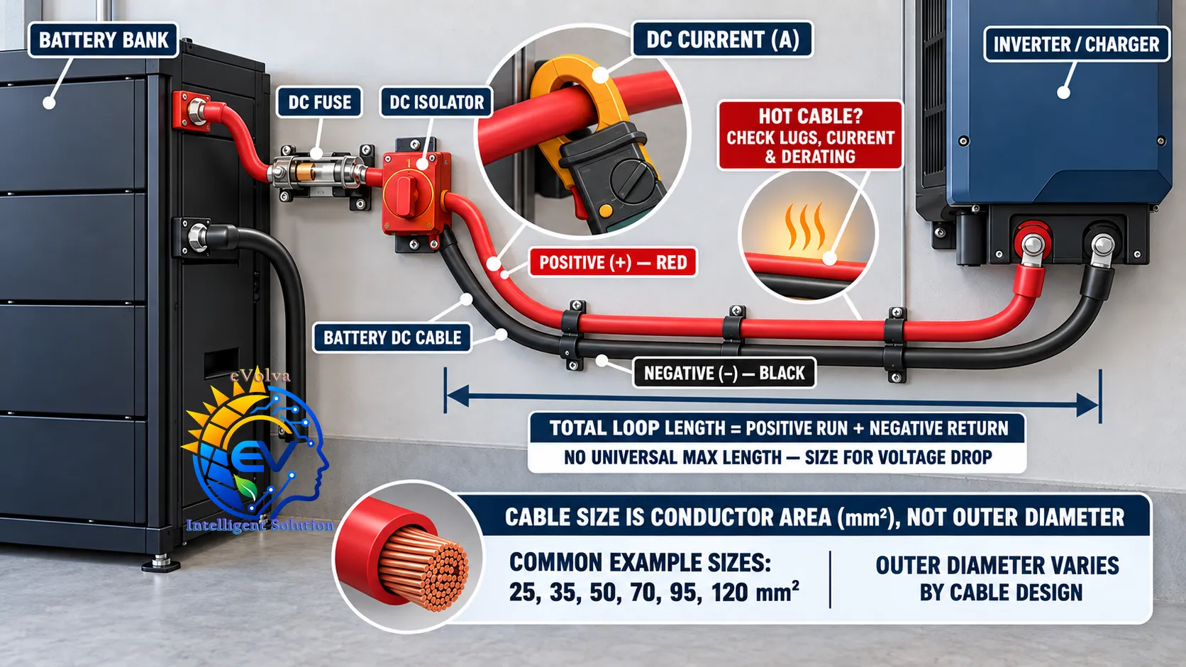
Battery cable selection considers the complete positive and negative path, current, voltage drop and DC protection.
What battery cable sizing must account for
Check
What to establish
Operating current
Maximum continuous discharge and charge current, plus any permitted overload or surge current. Use the equipment's specified DC current where available.
Minimum operating voltage
Battery voltage can fall under load. Calculate inverter current at its minimum permitted DC voltage, not only at nominal battery voltage.
Total cable length
Include the positive and negative runs. Include busbars, fuses, shunts, disconnects and other series components in the voltage-drop path.
Ampacity
Check the cable manufacturer's rating for the actual insulation, installation method, ambient temperature, grouping and enclosure. Apply all required derating factors.
Voltage drop
Keep the inverter voltage within its operating range and avoid excessive loss during both discharge and charging.
Fault protection
Coordinate the conductor with a correctly rated DC fuse or breaker, battery/BMS limits, inverter limits and the prospective short-circuit current.
Terminations
Match the cable strand class and cross-section to the inverter and battery terminals, lugs, crimp tool, stud size and tightening torque.
Estimate the battery-side current
For an inverter supplying AC power from a battery, a first estimate is:
DC current (A) ≈ AC output power (W) ÷ [battery voltage under load (V) × inverter efficiency]
Use the inverter's maximum DC input current if the manual provides it. The calculation is a cross-check; the actual maximum can depend on overload duration, DC voltage, power factor, temperature and the inverter's current limit. For a bidirectional inverter/charger, check maximum charge current separately and size for the more demanding direction.
Example: same power, different battery voltages
For an illustrative 5,000 W AC output and 94% inverter efficiency, current at nominal voltage is approximately:
Nominal battery voltage
Approximate DC current
24 V
222 A
48 V
111 A
96 V
55 A
As the battery voltage falls under load, current rises. For example, a 5,000 W inverter operating at 94% efficiency on a 42 V loaded DC bus would draw about 127 A. These values are examples only; the inverter, battery and BMS specifications determine the actual design current.
The table shows why a lower-voltage system may need much larger conductors for the same power. It does not establish an ampacity rating or a final cable size.
Calculate voltage drop over the battery loop
Battery current travels out through the positive cable and returns through the negative cable. If the two conductors have the same cross-section and length, use:
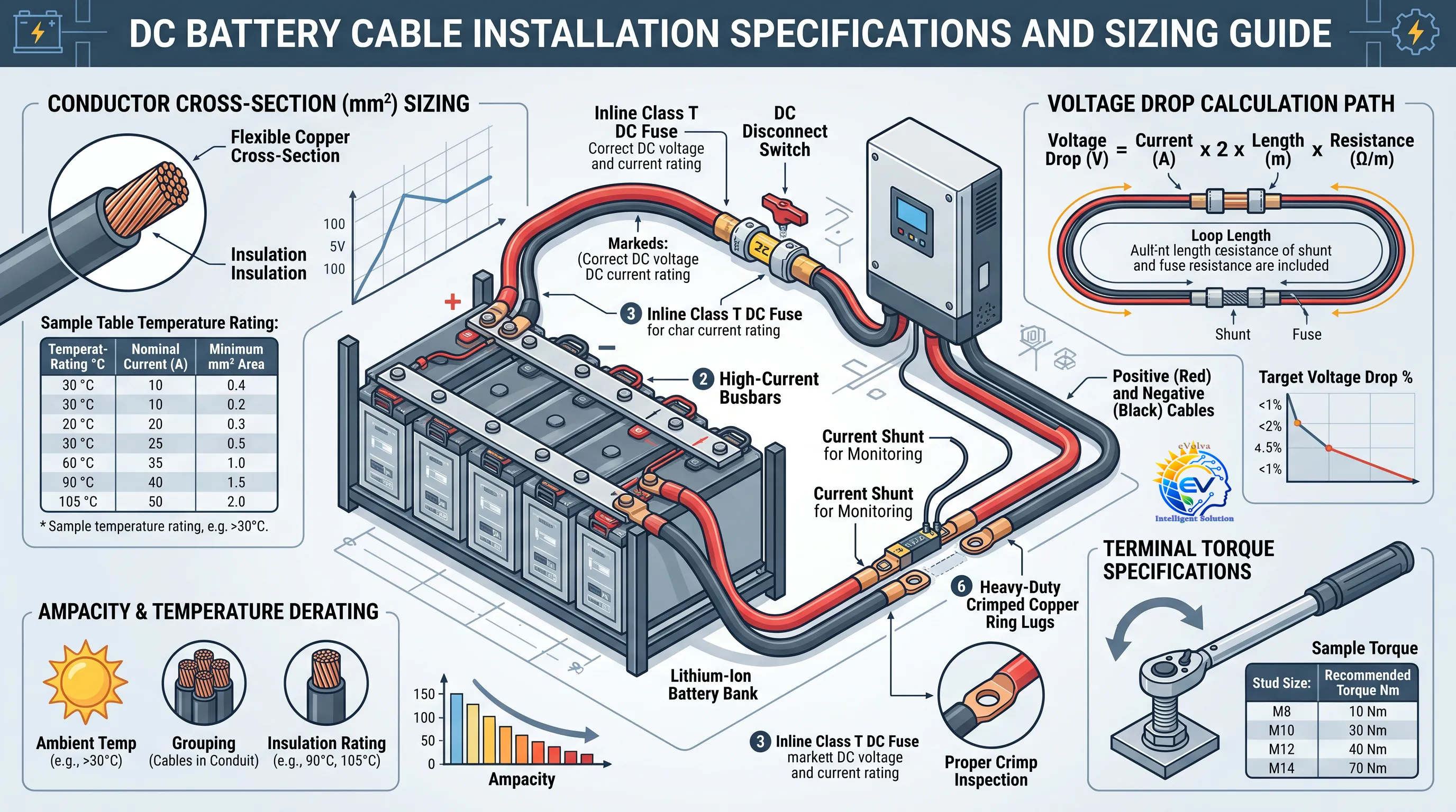
Voltage drop (V) = current (A) × 2 × one-way length (m) × resistance per metre (Ω/m)
Or, for different cable lengths or sizes:
Voltage drop (V) = current × (positive-cable resistance + negative-cable resistance)
Account for resistance in fuses, shunts, switches, busbars and contact points as well. Poor crimps, loose terminals and corrosion can add resistance and heating. Manufacturer guidance also emphasizes calculating the combined positive and negative cable length and checking voltage drop across the complete path. Victron Wiring Unlimited: DC wiring
Worked voltage-drop example
Assume a 127 A load, a 2 m positive cable and a 2 m negative cable. For illustration, assume the selected cable datasheet gives a conductor resistance of 0.39 Ω/km at 20°C. A simple copper temperature correction estimates about 0.50 Ω/km near 90°C.
Total cable length = 2 m + 2 m = 4 m.
Cable-only drop = 127 A × 4 m × 0.00050 Ω/m = 0.254 V.
On a 42 V loaded battery bus, that is approximately 0.60%.
This example checks voltage drop only. It does not prove that any particular cross-section has adequate ampacity for the route or coordinates with the fuse. Use the exact cable's maximum resistance, installation rating, actual conductor temperature and all series-component losses. IEC 60228 covers conductor cross-sections and resistance values, including flexible copper conductors and temperature-correction information. IEC 60228:2023
Choose a voltage-drop target
There is no single percentage that applies to every battery system. Follow the inverter and battery manufacturer's guidance and confirm that voltage at the equipment terminals remains within operating and charging limits during the highest expected current. As one example, Victron's Wiring Unlimited guide recommends aiming below 2.5%; this is manufacturer guidance, not a universal regulatory limit. It also notes that fuses, shunts and connections contribute to total resistance. Voltage-drop explanation and guidance
Nominal DC bus voltage
2.5% illustrative drop
12 V
0.30 V
24 V
0.60 V
48 V
1.20 V
Use actual battery voltage under load for the final percentage calculation. A cable-only calculation can understate total drop if it leaves out the fuse, shunt, disconnect, busbar and terminals.
Installation concept illustration. Printed sample sizes, chart values and tightening torques are illustrative; use the exact cable datasheet and equipment manuals for design and installation.
Select cable ampacity and construction
Do not use a universal “amps per mm²” rule as the final answer. Ampacity depends on cable insulation and strand construction, continuous conductor temperature, ambient heat, bundling, conduit, airflow, terminal temperature rating and the manufacturer's test conditions. A short cable can still overheat if the current exceeds its installation-specific rating.
Battery cables are often flexible copper conductors to make short, high-current connections practical. Select a cable with a declared DC voltage, temperature and environmental rating suitable for the system. Verify the strand class and lug are approved for the terminal. Welding or automotive cable is not automatically suitable for a stationary battery installation unless its ratings and applicable rules match the use.
The final cross-section must pass both checks:
Ampacity: carry the design current after all relevant correction factors.
Voltage drop: keep the battery-to-inverter voltage loss within the project target at the design current.
Then verify terminal fit, bending radius, mechanical support and protection coordination. The equipment manual may give its own cable-size and fuse table by model and cable length. For example, inverter manuals can specify different cross-sections and fuse values for 12 V, 24 V and 48 V versions of similar power ratings; follow the manual for the exact model. Manufacturer installation-manual example
Coordinate cable, fuse, battery and inverter
The fuse or breaker protects the conductor and equipment from overcurrent and short-circuit conditions. Select a device that is rated for DC use at the system voltage and has an interrupting capacity suitable for the battery's available fault current. Coordinate its rating and time-current behavior with:
Cable ampacity and installation derating
Battery continuous and peak current limits
Battery-management-system (BMS) limits and shutdown behavior
Inverter/charger maximum DC current and surge duration
Battery and inverter manufacturer's fuse requirements
Local electrical rules and the required fault-clearing behavior
Place protection and isolation as required by the equipment instructions and local rules, so the battery-side conductor is protected. Do not rely on a cable's cross-section, the inverter's internal protection or the BMS alone to resolve external cable-fault protection. Never replace a DC-rated protective device with an AC device unless it is explicitly rated for the DC circuit.
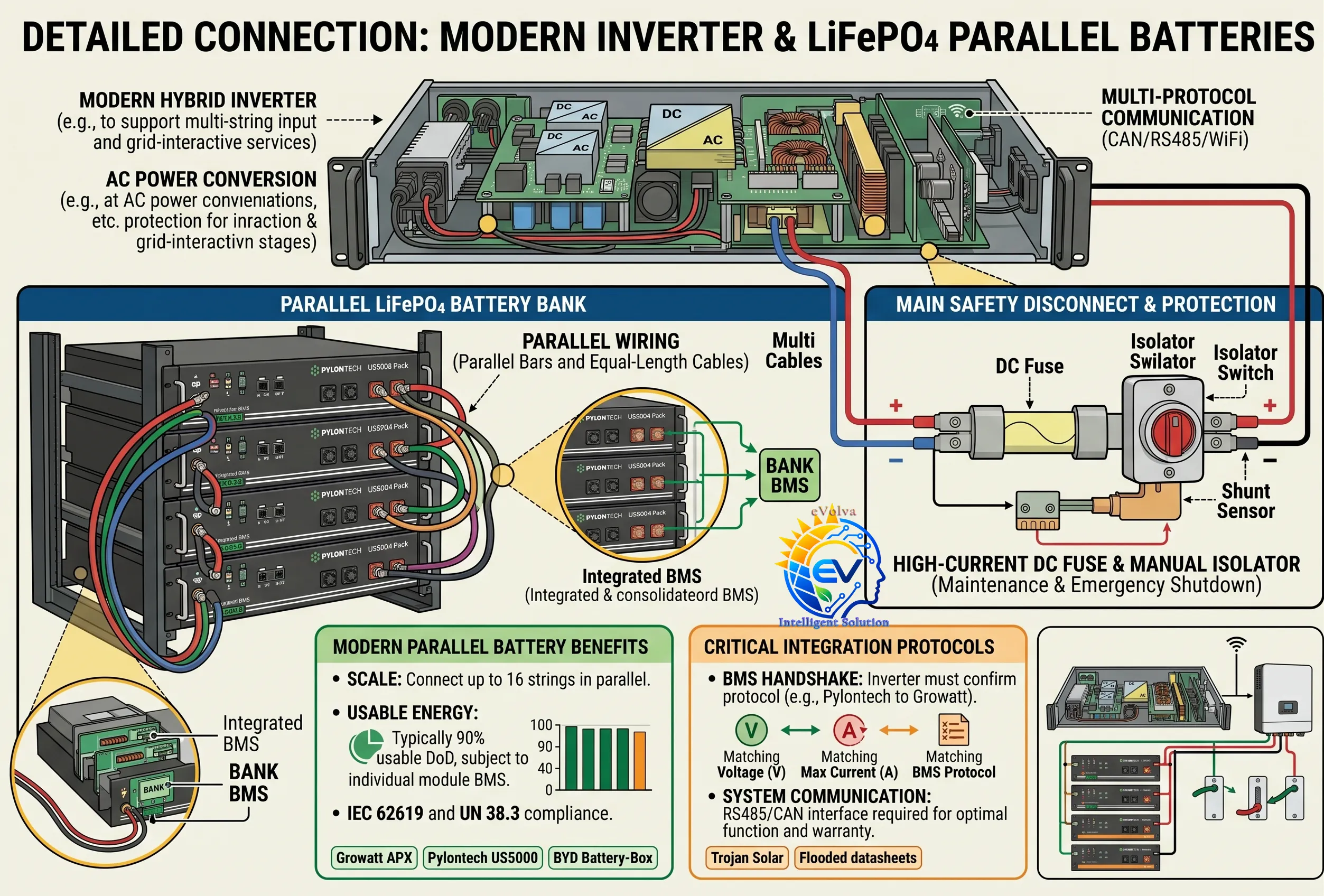
Parallel battery concept illustration. Connection limits, usable depth of discharge, communication compatibility and protection must follow the exact battery and inverter manuals; this image is not a wiring instruction.
Parallel batteries and DC busbars
For multiple parallel battery units, follow the battery manufacturer’s approved connection diagram. Use correctly rated busbars and design branch connections so the batteries share current as intended. Equal conductor size and comparable positive and negative path resistance are common ways to support current sharing; do not assume current divides equally if cable paths, connections or battery characteristics differ. Apply branch protection where required by the manufacturer and the project design.
Cover or guard exposed busbars and battery terminals against accidental short circuits. Use insulated tools, observe polarity, and follow the specified tightening torque. Battery banks can deliver very high fault current even when their nominal voltage is relatively low.
Installation and commissioning checks
Keep battery cables short and route positive and negative conductors together where practical.
Protect cables from abrasion, sharp edges, heat, moisture, movement and accidental contact with metalwork.
Use the specified cable lug, die and crimp tool; inspect the completed crimp and apply the manufacturer's terminal torque.
Avoid unnecessary joints and series components. Check fuse holders, shunts, disconnects and busbars for their current and voltage ratings.
Confirm polarity and isolation before connection. Follow the battery and inverter procedures for safe shutdown and reconnection.
Under a representative high-current charge or discharge, measure voltage at both ends of the cable path and inspect for abnormal heating at cable lugs, fuses and terminals.
Stationary battery installation standards address broader protection and installation hazards in addition to cable selection. IEC 60364-5-57:2022 covers the design, erection, use and protection of stationary secondary battery installations; battery chemistry and product standards also matter. Check the standards adopted in the project jurisdiction. IEC 60364-5-57 overview · IEC 62485-5:2020 for stationary lithium-ion battery installation safety
Common battery-cable applications
Battery bank to inverter/charger
Battery bank to a DC busbar, fuse or disconnect assembly
Interconnections between series or parallel battery units
Battery to charge controller or DC distribution equipment
Battery storage cabinets and stationary energy-storage systems
Frequently asked questions
Can I use the same cable-size table for PV strings and batteries?
No. PV string cables and battery cables have different current, voltage, route and installation conditions. The same voltage-drop equation can be used for either circuit, but the cable rating and protection design must match the specific application.
Should I size from the battery's nominal voltage?
Use the lowest voltage expected at the battery terminals under the design load when estimating inverter discharge current. Then confirm the current against the inverter and battery/BMS specifications.
Does a thicker cable always solve battery-cable problems?
A larger conductor can reduce resistance and heating, but it must fit the terminals and be installable within the equipment's bend limits. Voltage drop can also come from undersized fuses, poor crimps, loose terminals, shunts and switches. Check the whole current path.
Is the negative battery cable the same as protective earth?
No. The battery negative conductor is part of the normal DC circuit. Protective-earth and bonding conductors serve a separate safety function and must be selected under the equipment instructions and applicable electrical rules.
Final selection checklist
Before ordering, record the inverter's maximum DC current, the battery's continuous and peak charge/discharge limits, minimum loaded voltage, cable one-way route length in both polarities, cable resistance and installation ampacity, voltage-drop target, fuse/breaker type and rating, terminal/lug requirements, and the applicable local rules. Document the selected cable and protective device for each battery connection on the drawings.
This article is general design guidance. Final battery-cable and protection selection must be checked against the exact battery, inverter/charger, cable, installation conditions and local requirements by a qualified electrical designer.
ဗဟုသုတ · Battery DC Cable
ဘက်ထရီ DC ကေဘယ်ရွေးချယ်ခြင်း — လျှပ်စီး၊ ကြိုးအရွယ်အစား၊ ဗို့အားကျဆင်းမှုနှင့် ကာကွယ်ရေး
ဝန်ရှိလျှင် ဘက်ထရီဗို့အားကျနိုင်သည်။ Nominal ဗို့အားတစ်ခုတည်းမသုံးဘဲ inverter ခွင့်ပြုသော အနိမ့်ဆုံး DC ဗို့အားဖြင့် လျှပ်စီးတွက်ပါ။
ကြိုးစုစုပေါင်းအရှည်
အပေါင်းနှင့် အနုတ်လမ်းကြောင်း နှစ်ဖက်လုံးပါဝင်ရမည်။ Voltage drop လမ်းကြောင်းတွင် busbar၊ fuse၊ shunt၊ disconnect နှင့် အခြား series ပစ္စည်းများ ထည့်တွက်ပါ။