PV cells convert light into direct-current electricity. Rated watts are measured under standard test conditions; real output changes with irradiance, temperature, shade and dirt.
Myanmar solar energy planning baseline
Solar PV, Inverter and Battery Information & System Design
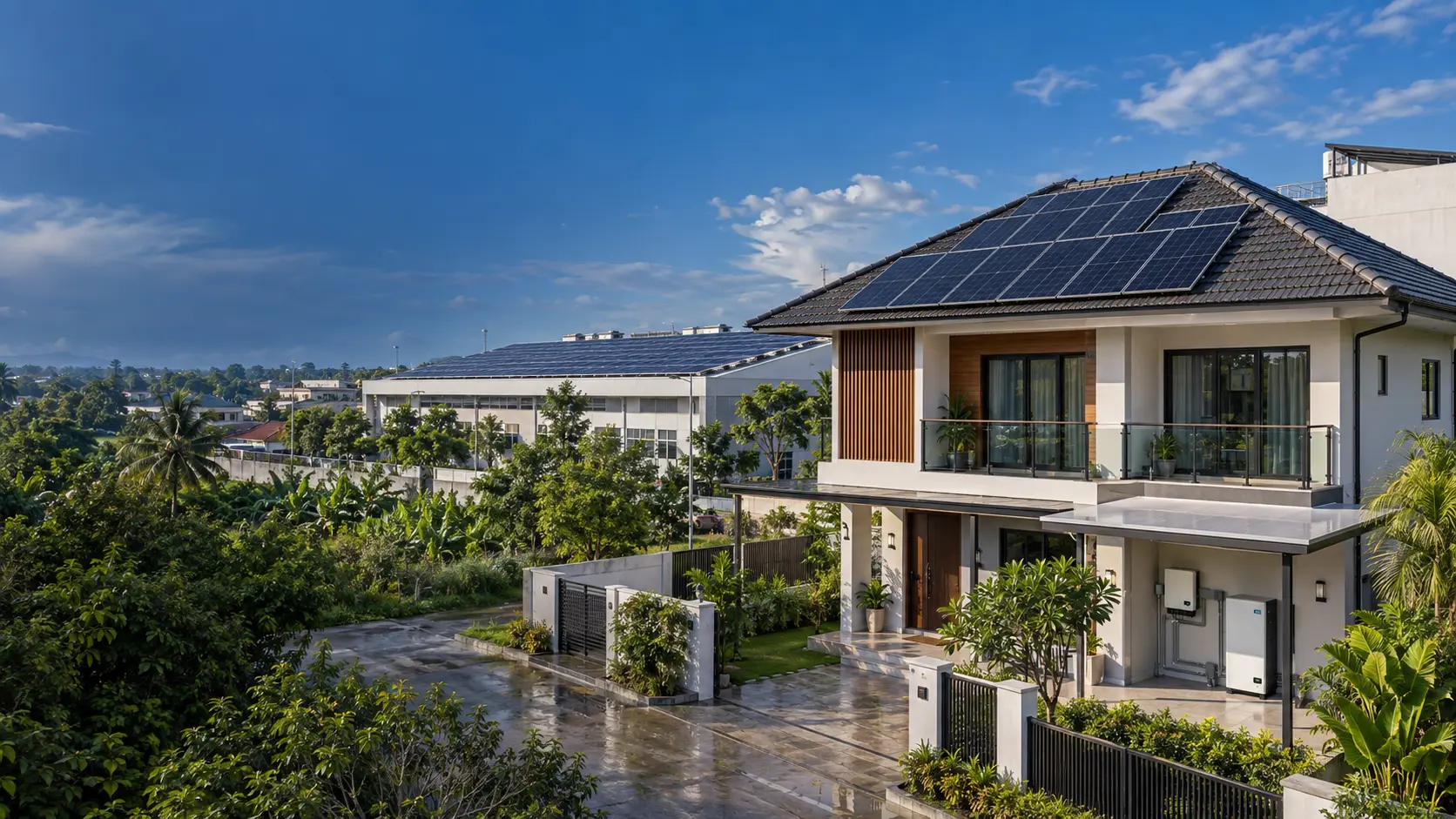
Why renewable energy matters
Solar energy turns sunlight into electricity that can support everyday life and productive work. Renewable energy also includes wind, hydropower and other sources that are naturally replenished. For Myanmar, where reliable electricity can be difficult to access, solar offers another way to meet local energy needs.
Rooftops and suitable land can produce power close to the homes and businesses that use it. Solar can help schools, clinics, farms and workshops continue essential activities when a system includes suitable backup. Batteries can store some daytime production for use later, within their capacity and operating limits.
Changing fuel prices and uncertainty in global supply chains make a more diverse energy supply valuable. Using renewable electricity can reduce dependence on fuel deliveries and lower emissions during operation. Good results depend on measured energy needs, suitable equipment, careful installation and regular maintenance. Learning these technologies helps communities make informed choices and build practical skills for a cleaner energy future.
For Myanmar youth and skilled workers
This free guide is for Myanmar youth and skilled workers learning or working locally and abroad. Follow the path from solar basics and energy estimation to equipment selection, wiring, protection and planning small to medium projects. Explore the local solar market, compare supplier information and learn what to check before buying or installing equipment.
For households and curious learners
Households and general readers can also learn how solar works, understand energy use and backup limits, and discuss proposals with installers. Learn free in English or Myanmar, with references to industry standards such as IEC for further study. Estimates are starting points; final electrical and structural designs need a site survey and qualified professional review.
Quick Estimate
QUICK ESTIMATE
Adjust the five inputs for an initial array, inverter and battery estimate. Use Detailed sizing for location, equipment, wiring and a bill of materials.
Installed array5.50 kWp10 × 550 W modules
Nominal battery21.7 kWhbefore project-specific reserve
Inverter minimum5.0 kWsingle-phase candidate
Indicative roof area29 m²includes 15% access allowance
Annual PV energy7,975 kWhpreliminary planning estimate
Hybrid mode supports solar self-use, battery backup and grid or generator input.
Solar power basics
How sunlight becomes usable electricity
The inverter continuously adjusts PV voltage and current to operate near the array's maximum power point.
DC becomes synchronized AC for appliances, motors and distribution boards. A hybrid inverter can also charge a battery and coordinate the grid or generator.
Loads normally use solar first. Surplus may charge the battery or export where permitted; shortages come from the battery, grid or generator according to control settings.
Daily energy ≈ array kWp × peak-sun-hours × performance ratio
5.5 kWp × 5.0 h × 0.78 ≈ 21.5 kWh/dayIllustrative clear-season day; monthly weather changes the result.
Reference configurations
Nine scalable system classes
| Use case | PV | Example modules | Inverter | Battery planning range | Electrical form |
|---|---|---|---|---|---|
| 3–20 kWpHouses, villas, small home offices | |||||
| Essential home | 3.3 kWp | 6 × 550 W | 3–5 kW hybrid | 5–10 kWh | Single phase |
| Standard home | 5.5 kWp | 10 × 550 W | 5–6 kW hybrid | 10–15 kWh | Single phase |
| Large home or shop | 10.8 kWp | 18 × 600 W | 10 kW hybrid | 15–30 kWh | Single or three phase |
| 20–100 kWpShops, offices, restaurants, clinics | |||||
| Small business | 20.4 kWp | 34 × 600 W | 20 kW three phase | 30–60 kWh | Three phase preferred |
| Commercial facility | 50.4 kWp | 84 × 600 W | 50 kW three phase | 80–150 kWh | Three phase |
| 100–500 kWpHotels, schools, warehouses, shopping centres | |||||
| Medium C&I | 100.8 kWp | 168 × 600 W | 100 kW or 2 × 50 kW | 160–300 kWh | Three phase with protection study |
| Medium C&I facility | 250 kWp | 400 × 625 W | 2 × 125 kW | Project-specific BESS sizing | Three phase; protection and interconnection study |
| 500 kWp–1 MW+Factories, industrial plants, large warehouses | |||||
| Industrial facility | 500 kWp | 800 × 625 W | 4 × 125 kW | Project-specific BESS sizing | Three phase; protection and interconnection study |
| Large industrial / campus | 1,000 kWp (1 MWp) | 1,600 × 625 W | 8 × 125 kW | Project-specific BESS sizing | Three phase; protection and interconnection study |
Battery ranges are examples for critical-load backup, not fixed bills of materials. An energy audit must separate essential loads from air-conditioning, water heating, pumps and industrial motors.
Technology selection
Match module size to the structure
Residential roof class
Easier handling, flexible roof layouts and broad compatibility with residential inverters.
Commercial roof class
Fewer modules and connections per kWp, but larger dimensions and higher string current require careful engineering.
Large-format engineered class
Best considered for ground mounts or engineered large roofs. Verify commercial availability, dimensions, wind loading, clamp zones and inverter current limits.
Recommended modern baseline
- N-type TOPCon or HJT modules with IEC 61215 and IEC 61730 certification
- MPPT hybrid or grid inverter with local service support and documented battery compatibility
- LiFePO₄ storage with cell monitoring, BMS, DC isolation and IEC 62619 evidence
- Remote monitoring, generator integration and export limiting where required
Connection reference
Accessories, wiring and grounding guide
Cable size is determined from current, voltage, installation method, ambient temperature, grouping, voltage drop and fault withstand—not from system kW alone.
| Circuit | Cable / connection | Accessories | Installation rule |
|---|---|---|---|
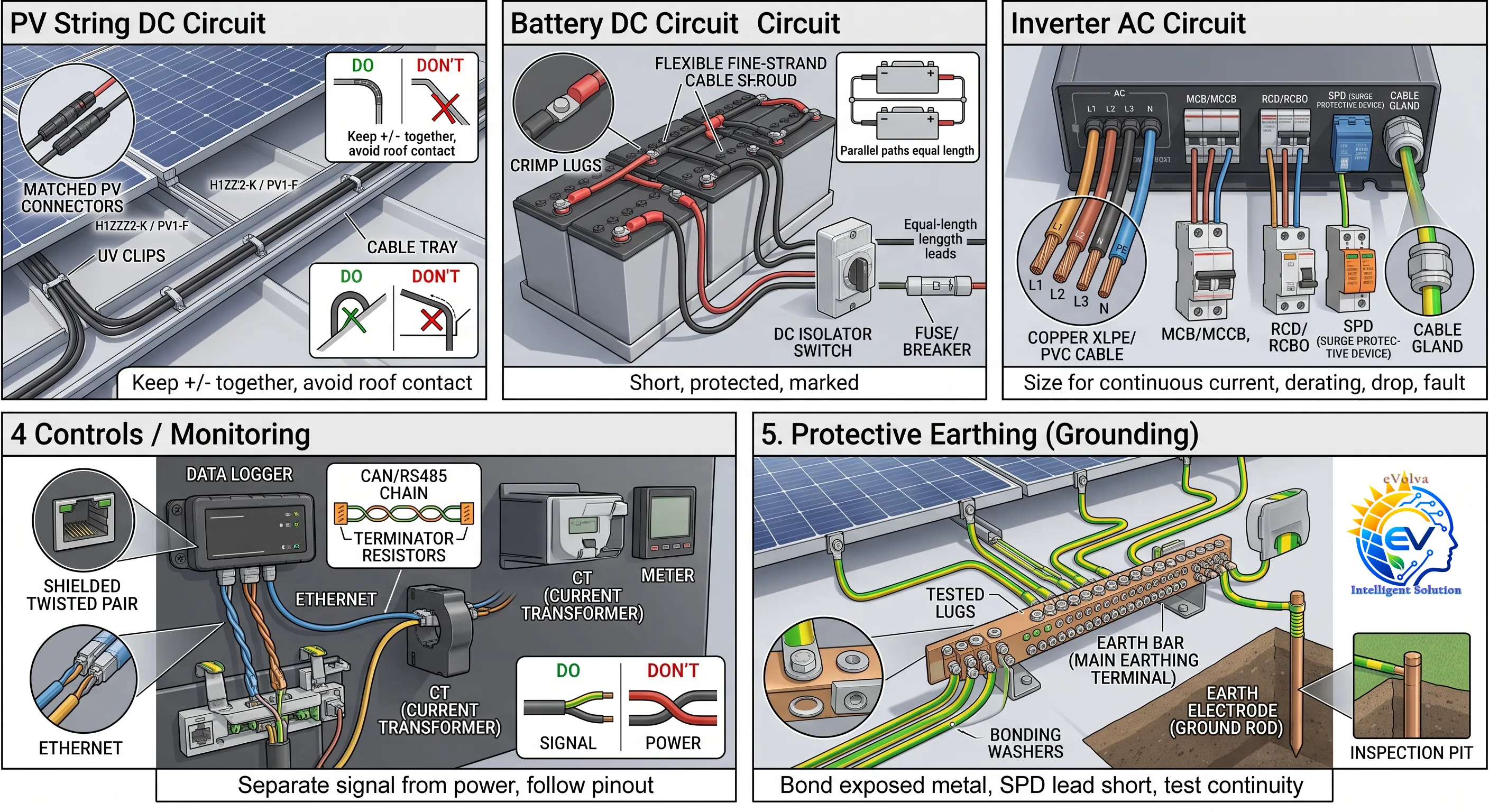
| H1Z2Z2-K / PV1-F copper solar cable | Matched PV connectors, UV clips, conduit/tray, labels | Keep +/− together, avoid roof contact and sharp bends; never mix connector brands. | |
| Manufacturer harness or flexible fine-strand copper battery cable | Crimp lugs, shrouds, fuse/breaker, DC isolator, busbar | Use short, protected, polarity-marked conductors; parallel paths must be equal length. | |
| Copper XLPE/PVC cable with the required phase, neutral and PE cores | MCB/MCCB, isolator, RCD/RCBO, SPD, gland | Size for continuous current, derating, voltage drop and short-circuit withstand. | |
| Specified CAN/RS485 cable, shielded twisted pair or Ethernet | CT, meter, terminators, dry-contact relay, data logger | Separate signal cable from power; follow the manufacturer pinout and shield instructions. | |
| Green/yellow copper PE and equipotential bonding conductor | Earth bar, tested lugs, bonding washers, electrode, inspection pit | Bond exposed metal and keep SPD earth leads short; test continuity and earth resistance. |
Cables & Cable Size Selection
Solar systems use four cable paths: PV string DC, battery DC, inverter AC and PE / bonding. Choose the correct cable type and size for each circuit using current, voltage, route length and installation conditions. System kWp alone does not determine cable size.
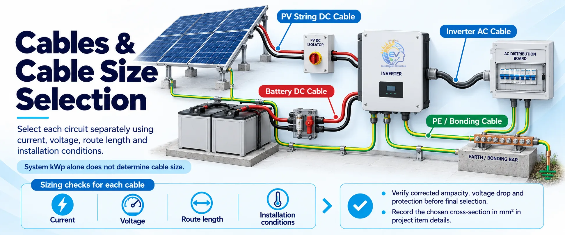
| Circuit | Selection checks / စစ်ဆေးရန် |
|---|---|
| PV String DC Cable | PV-rated insulation, voltage and temperature rating; matched connectors and protected routing. |
| Battery DC Cable | Manufacturer cable requirements, peak current, total positive and negative cable length, voltage drop and fuse coordination. |
| Inverter AC Cable | Phase arrangement, continuous current, derating, voltage drop, terminal compatibility and fault withstand. |
| PE / Bonding Cable | Applicable design rules and equipment requirements for protective and bonding conductors. |
Verify corrected current-carrying capacity, voltage drop and protection before final selection. Record the chosen cross-section in mm² in project item details.
Cable reference · Victron Wiring UnlimitedCable sizing training guide
Worked values compare voltage drop only; they are not approved installation sizes. Complete ampacity, derating, fault, protection and terminal checks before final selection.
Cable sizing workflow

PV, battery, AC and PE circuits

Voltage-drop comparison examples

Read the full guide, calculations and commissioning checklist
Why cable sizing is a circuit-by-circuit task
A cable must carry the circuit’s design current under the actual installation conditions, keep voltage drop within the project limit, withstand the expected fault until protection operates, and connect safely to the equipment terminals. A cable that passes one check can still fail another.
That is why a 20 kWp, 100 kWp or 1 MWp PV label cannot directly specify a conductor size. A PV string, a low-voltage battery lead, a three-phase inverter feeder and a protective-earth conductor do different jobs. Each needs its own calculation and cable schedule.
1. Read the cable size correctly
The value in mm² is the conductor’s nominal cross-sectional area, not the cable’s outside diameter. The same nominal area can be supplied in different conductor materials, strand classes, insulation systems, voltage ratings and temperature ratings. IEC 60228 defines nominal conductor areas and conductor resistance; the product datasheet still determines the properties of the exact cable selected. IEC 60228:2023
Common metric sizes include 1.5, 2.5, 4, 6, 10, 16, 25, 35, 50, 70, 95, 120, 150, 185 and 240 mm². This is a list of familiar nominal sizes—not a current-capacity table. Do not infer that a given size is suitable for a particular current without the cable type, installation method, ambient temperature, grouping and protection design.
2. Separate the four cable circuits
| Circuit | What it does | Main sizing checks |
|---|---|---|
| PV string DC | Connects a module string to an inverter MPPT or combiner. | Maximum PV voltage, string design current, cable certification, UV/weather exposure, route length, connector match, ampacity and DC voltage drop. |
| Battery DC | Connects a battery or BESS to its inverter or power-conversion system. | Minimum operating battery voltage, maximum continuous and surge current, charge/discharge direction, total positive-plus-negative length, voltage drop, fuse/disconnect coordination and BMS limits. |
| Inverter AC | Connects inverter output to a switchboard, loads, grid or generator interface. | Single/three-phase arrangement, nameplate output current, power factor, harmonics, route and grouping, voltage drop or voltage rise, terminal limits and fault protection. |
| PE / bonding | Provides protective continuity between exposed conductive parts and the designed earthing system. | Fault current and clearing time, protective device, earthing arrangement, mechanical strength, corrosion, connection method and applicable protective-conductor rules. |
PV array wiring, switching and earthing have PV-specific design requirements. The IEC catalogue lists IEC 62548-1:2023+AMD1:2025 for PV-array design and IEC 60364-7-712:2025 for PV electrical installations, including relevant storage provisions. General wiring systems and protective conductors are addressed by IEC 60364-5-52 and IEC 60364-5-54. These standards are references for qualified designers; project teams must confirm which editions and local rules apply. IEC 62548-1 · IEC 60364-7-712 · IEC 60364-5-52 · IEC 60364-5-54
3. Use a repeatable sizing sequence
- Define one circuit at a time. Mark the source, destination, voltage, operating modes and protective devices. Give each string, battery branch and AC feeder its own line in the schedule.
- Measure the actual route. Measure the cable path, including rises, drops, turns and service allowance. For a two-wire DC circuit, record both the positive and negative conductors: the electrical loop is longer than the one-way route. Note whether the route is in free air, on a tray, in conduit, within a hot roof space, buried in soil or grouped with other loaded cables.
- Find the design current and voltage. Use module, inverter, battery and BMS documentation plus the applicable design rules. For PV, a string and a parallel-string trunk do not carry the same current. For a battery inverter, use the lowest operating DC voltage and account for conversion losses. For an AC inverter, use its rated maximum continuous output current and the actual phase arrangement.
- Choose a cable product for the environment. Check conductor material and class, insulation, voltage rating, conductor temperature rating, UV and water exposure, chemicals, abrasion, rodents, fire requirements, bending radius and terminal compatibility. On the PV DC side, select a cable designed and certified for PV service, not an ordinary building wire chosen only because its cross-section looks sufficient. IEC 62930 covers specified single-core cross-linked cables used on the DC side of PV systems up to 1.5 kV DC. IEC 62930:2017
- Check current-carrying capacity after derating. Start with the ampacity data for the exact cable and its installation method. Apply the correction factors required for ambient temperature, grouping, enclosure or conduit, roof heat, soil conditions and other relevant influences. The resulting permitted current is often denoted Iz. Where an overcurrent device is used, coordinate the design current, device and corrected cable capacity under the applicable rules; a common check is Ib ≤ In ≤ Iz. Confirm the device’s voltage and interrupting ratings separately.
- Calculate voltage drop and, on AC PV output, voltage rise. Use the cable’s resistance and reactance at the expected operating temperature, not just a cold-conductor value. Check the full path against the project’s permitted limit. There is no single percentage that is correct for every circuit, equipment manufacturer or jurisdiction.
- Verify fault withstand and disconnection. Confirm that the conductor can withstand the fault energy until the protective device clears it, and check fault duty, clearing time and selectivity in grid, inverter, battery and generator modes. Inverters may limit fault current, so do not assume grid-mode protection behavior will also apply in backup mode. A common adiabatic check is I²t ≤ k²S²; the correct fault current, clearing time and material/insulation factor must come from design data and governing rules.
- Check the connection, then document it. Confirm terminal range, lug or ferrule type, crimp tooling, torque value, bend radius, support and labels against manufacturer instructions. Keep BMS, metering and communication wiring as separate control circuits, routed and shielded as the equipment instructions require. Record the cable ID, type, size, route, design current, derating assumptions, voltage-drop result, protective device and test results.
4. Understand the calculation inputs
Current starting points
Battery DC: for an inverter delivering AC power, a first estimate is I ≈ PAC / (VDC,min × η). Confirm against maximum battery and inverter currents and the BMS limits.
AC current: single phase I ≈ P / (V × PF × η); balanced three phase I ≈ P / (√3 × VL-L × PF × η). If P is already the inverter’s AC output, omit η. Check the inverter’s rated maximum output current as well.
PV string: determine design current from module data, parallel-string count, inverter inputs and applicable PV rules. Do not use module wattage alone.
Voltage-drop starting points
Two-wire DC: ΔV ≈ I × (2L) × R / 1000, when R is in Ω/km and L is the one-way length in metres.
Single-phase AC: ΔV ≈ 2 × I × L × (R cosφ + X sinφ). Balanced three-phase AC: ΔV ≈ √3 × I × L × (R cosφ + X sinφ), with one-way L in km and R/X in Ω/km.
Use the exact conductor resistance and impedance tables for the selected cable. Include connections and operating temperature where required. Manufacturer battery-wiring guidance also treats the positive and negative cable lengths together when calculating DC drop. Victron, Wiring Unlimited
5. Worked examples: compare sizes, then complete the checks
The comparisons below use example copper-conductor resistance values at 20°C from a cable product data table. They isolate the resistance-based voltage-drop effect so trainees can see how size and length interact. The values are not current ratings. Actual PV cable data, conductor operating temperature, reactance, connector/contact resistance and installation corrections can change the result. Example conductor resistance data
Example A · PV string DC
Assume a 13 A string design current, 500 V operating string voltage, and a 30 m one-way route. The positive and negative conductors create a 60 m loop. With ΔV = I × 2L × R / 1000:
| Copper area | R at 20°C | Calculated drop | Drop as % of 500 V |
|---|---|---|---|
| 4 mm² | 4.61 Ω/km | 3.60 V | 0.72% |
| 6 mm² | 3.08 Ω/km | 2.40 V | 0.48% |
| 10 mm² | 1.83 Ω/km | 1.43 V | 0.29% |
This comparison does not decide which cable to install. Check the selected PV cable’s current capacity under rooftop temperature and grouping, maximum DC voltage, connector compatibility, mechanical protection and the actual voltage-drop criterion.
Example B · Battery DC
Assume a 5 kW AC inverter, 44 V minimum battery voltage and 92% conversion efficiency. The estimated battery current is 5,000 / (44 × 0.92) ≈ 124 A. With a 2 m one-way route, the positive-plus-negative loop is 4 m.
| Copper area | R at 20°C | Calculated drop | Drop as % of 44 V |
|---|---|---|---|
| 25 mm² | 0.727 Ω/km | 0.36 V | 0.82% |
| 35 mm² | 0.524 Ω/km | 0.26 V | 0.59% |
| 50 mm² | 0.387 Ω/km | 0.19 V | 0.44% |
At low DC voltage, inverter power can produce very high battery current. Check the manufacturer’s maximum battery current, battery BMS limit, DC-rated fuse or breaker, short-circuit rating, lug and terminal range, and the cable’s corrected ampacity. Keep the battery lead length short where the equipment design permits.
Example C · Three-phase inverter AC
Assume a 20 kW inverter on a 400 V three-phase system at power factor 0.98. Its calculated current is about 29.5 A. For a 25 m one-way cable route, a simplified resistance-only estimate gives:
| Copper area | R at 20°C | Approx. drop* | Drop as % of 400 V |
|---|---|---|---|
| 4 mm² | 4.61 Ω/km | 5.76 V | 1.44% |
| 6 mm² | 3.08 Ω/km | 3.85 V | 0.96% |
| 10 mm² | 1.83 Ω/km | 2.29 V | 0.57% |
*This simplified comparison includes R and power factor but omits cable reactance and temperature rise. Check the full three-phase impedance calculation, corrected ampacity, inverter current, voltage rise during export, harmonics, switchboard and protection before choosing a size.
6. Size PE and bonding conductors from the protection design
What PE means
PE means Protective Earth (ကာကွယ်ရေးမြေချိတ်ကြိုး). It links exposed conductive parts to the installation’s PE bar, providing a fault path for protective disconnection. It normally carries no load current. Distinguish it from Neutral, PV negative and the earthing conductor to an earth electrode.
A common copper PE sizing guide
| Phase conductor S | Example copper PE size |
|---|---|
| S ≤ 16 mm² | Same size as phase conductor |
| 16 < S ≤ 35 mm² | 16 mm² |
| S > 35 mm² | Half the phase conductor size |
Examples: 10 mm² phase → 10 mm² PE; 25 mm² phase → 16 mm² PE; 50 mm² phase → 25 mm² PE. This simplified method assumes the same conductor material and matching design conditions. A separately run copper PE has minimum sizes of 2.5 mm² with mechanical protection or 4 mm² without it; fault and disconnection checks may require more. Schneider Electric: PE sizing guide
Solar equipment and fault checks
Verify the required cross-section using the applicable table or fault calculation, including clearing time, material and insulation. IEC 60364-5-54 addresses protective conductors and bonding; IEC 60364-7-712 addresses PV installations. Check the exact equipment instructions for frames, rails, inverter chassis, battery cabinet and switchboard. Do not assume one size suits all parts or bond PV negative or Neutral to PE unless the approved design and equipment instructions require it.
IEC 60364-5-54 · Example model-specific chassis earthing instructions
Protective earth (PE) is not a normal load conductor. Its job is to provide a reliable fault-current path and support the required protective disconnection. Select PE and bonding conductors using the applicable installation rules, protective-device characteristics, fault current and clearing time, mechanical protection and corrosion conditions. Do not copy the PV positive cable size, assume every frame bond is 6 mm², or treat an earth electrode as a substitute for the required PE path. IEC 60364-5-54 covers earthing arrangements and protective conductors, including protective bonding conductors. IEC 60364-5-54
Bond exposed conductive parts as the design requires: module frames, mounting rails, inverter enclosure, battery cabinet and switchboard enclosure. Use approved hardware, compatible metals and inspectable connections. Verify continuity across joints and document the main earthing terminal and test results.
7. Conditions that often increase the required size
- Long route: resistance and voltage drop rise with conductor length. Battery circuits are especially sensitive because their operating voltage is low.
- Hot roof or conduit: conductor temperature rises and the allowable ampacity falls. Rooftop cable may experience a hotter environment than nearby air temperature suggests.
- Grouped cables: cables that heat one another may need ampacity derating. A drawing should show how many loaded conductors share each conduit or tray section.
- High fault level or slow clearing: the conductor’s short-circuit withstand and the protective device’s operation can control selection even when voltage drop is small.
- Inverter export: AC voltage rise can limit PV output or cause disconnection. The route, conductor impedance and point of connection matter.
- Terminal limits: a cable that is electrically adequate may not fit the inverter or breaker terminals, bend radius, lug or connector. Follow the exact equipment manual.
- Weather and mechanical exposure: sunlight, rain, flooding, corrosion, vibration, sharp edges, pests and maintenance access affect cable type, routing and protection.
For larger commercial systems, the design may use parallel cable runs. Use them only where the governing rules and equipment allow it. The designer must check current sharing, matching conductor material and area, route and length, terminations, phase or polarity arrangement, protection and any magnetic-heating effects. Adding a second cable is not automatically equivalent to one cable of twice the area.
8. Avoid these common mistakes
- Choosing a cable from PV kWp alone.
- Using one-way length for a two-wire DC voltage-drop calculation.
- Reading an ampacity table for open air when the cable is bundled or enclosed.
- Assuming a familiar size has the same current rating in every cable type.
- Applying one voltage-drop percentage to every circuit without checking the project requirement.
- Ignoring battery minimum voltage, BMS current and DC fuse interrupt rating.
- Using building wire in an exposed PV route or mixing connector families.
- Skipping PE continuity, fault clearing and documentation checks.
9. Cable schedule and commissioning checklist
For every cable run, record: circuit ID; from/to; AC or DC; polarity/phase; cable product and standard; conductor material and mm²; number of parallel runs; actual route length and method; design current and voltage; ambient/grouping correction factors; corrected ampacity; voltage-drop result; protective device and settings; fault withstand; terminal and torque references; label; and test status.
- Inspect cable markings, rating, route support, bend radius, separation and mechanical protection.
- Verify polarity and phase sequence, protective-conductor continuity, insulation results and required protective-device operation using the approved commissioning procedure.
- Check lugs, ferrules and PV connectors are the correct type and are installed with the specified tool and torque.
- Under controlled operation, compare current and voltage readings with the design assumptions; investigate unexpected drop or heating.
- Hand over the cable schedule, as-built routes, protection settings, test records, equipment manuals and maintenance instructions.
Safety boundary: PV conductors can remain energized in daylight, and battery systems can deliver very high fault current. Isolation, proving dead, arc and shock protection, and energized testing must follow the equipment instructions and applicable safe-work procedures. Do not unplug PV connectors under load unless the connector is specifically rated for that operation. Use qualified electrical personnel for design, installation and commissioning.
Key lesson
Choose a cable only after it passes all required checks: current capacity after derating, voltage drop or rise, fault withstand and protection, voltage and temperature rating, environment, terminals and installation rules. The correct answer may be larger than the voltage-drop calculation alone suggests—and it must be recorded so the system can be inspected and maintained.
ဆိုလာစနစ်တွင် ကေဘယ်ကို ဘာကြောင့် ဆားကစ်တစ်ခုချင်းစီ စစ်ဆေးရသလဲ
ကေဘယ်တစ်ချောင်းသည် သတ်မှတ်ထားသော လျှပ်စီးကြောင်းကို အမှန်တကယ်တပ်ဆင်မည့် အခြေအနေတွင် သယ်ဆောင်နိုင်ရမည်၊ ဗို့အားကျဆင်းမှုကို သတ်မှတ်ကန့်သတ်ချက်အတွင်း ထိန်းထားနိုင်ရမည်၊ fault ဖြစ်သည့်အခါ ကာကွယ်ရေးပစ္စည်း အလုပ်လုပ်သည်အထိ ခံနိုင်ရမည်၊ စက်ကိရိယာ terminal နှင့်လည်း လုံခြုံစွာ ချိတ်ဆက်နိုင်ရမည်။ စစ်ဆေးချက်တစ်ခု အောင်ခြင်းဖြင့် အခြားစစ်ဆေးချက်များကို အစားထိုး၍ မရပါ။
ထို့ကြောင့် 20 kWp၊ 100 kWp သို့မဟုတ် 1 MWp ဆိုသည့် စနစ်အရွယ်အစားတစ်ခုတည်းဖြင့် ကေဘယ်အရွယ်အစားကို မရွေးနိုင်ပါ။ PV string, battery DC, inverter AC နှင့် PE/bonding တို့သည် လုပ်ဆောင်ချက်မတူသည့် ဆားကစ်များဖြစ်၍ သီးခြားတွက်ချက်ရပါမည်။
1. ကေဘယ်အရွယ်အစားကို ဖတ်နည်း
mm² သည် conductor ၏ အမည်ခံ ဖြတ်ပိုင်းဧရိယာဖြစ်ပြီး ကေဘယ်အပြင်ဘက်အချင်း မဟုတ်ပါ။ mm² တူသော်လည်း ကြေးနီ/အလူမီနီယမ်၊ conductor ကြိုးမျှင်အမျိုးအစား၊ insulation၊ ဗို့အားနှင့် အပူချိန်အဆင့် မတူနိုင်ပါ။ IEC 60228 တွင် conductor အမည်ခံအရွယ်အစားနှင့် resistance ဆိုင်ရာ သတ်မှတ်ချက်များ ပါရှိသော်လည်း ရွေးထားသည့် ထုတ်ကုန်၏ datasheet ကို အတည်ပြုရပါမည်။
အသုံးများသော metric အရွယ်အစားများမှာ 1.5၊ 2.5၊ 4၊ 6၊ 10၊ 16၊ 25၊ 35၊ 50၊ 70၊ 95၊ 120၊ 150၊ 185 နှင့် 240 mm² တို့ဖြစ်သည်။ ဤစာရင်းသည် ပုံမှန်အမည်ခံအရွယ်အစားများသာဖြစ်ပြီး လျှပ်စီးကြောင်းဇယား မဟုတ်ပါ။ တပ်ဆင်နည်း၊ အပူချိန်၊ စုစည်းတပ်ဆင်မှုနှင့် ကာကွယ်ရေးပစ္စည်းကို မစစ်ဘဲ mm² တစ်ခုကို သင့်လျော်သည်ဟု မယူဆပါနှင့်။
2. ဆားကစ်လေးမျိုးနှင့် အဓိကစစ်ဆေးချက်များ
| ဆားကစ် | အဓိကစစ်ဆေးချက် |
|---|---|
| PV string DC | PV အများဆုံးဗို့အား၊ string current၊ PV အတွက် သတ်မှတ်ထားသော cable၊ နေရောင်/မိုးရေခံနိုင်မှု၊ connector ကိုက်ညီမှု၊ ampacity နှင့် DC ဗို့အားကျဆင်းမှု။ |
| Battery DC | အနိမ့်ဆုံး battery voltage၊ အများဆုံး ဆက်တိုက်/ခဏတာ current၊ အပေါင်းနှင့် အနှုတ်ကြိုးစုစုပေါင်းအရှည်၊ voltage drop၊ fuse/breaker နှင့် BMS limit။ |
| Inverter AC | တစ်ဖေ့စ်/သုံးဖေ့စ်၊ inverter rated current၊ power factor၊ harmonic၊ ကြိုးလမ်းကြောင်းနှင့် စုစည်းမှု၊ voltage drop/rise၊ terminal နှင့် fault protection။ |
| PE / bonding | fault current၊ protection ဖြတ်တောက်ချိန်၊ earthing arrangement၊ ခိုင်ခံ့မှု၊ corrosion နှင့် သက်ဆိုင်ရာ protective-conductor စည်းမျဉ်းများ။ |
PV array ကြိုးချိတ်ခြင်း၊ switching နှင့် earthing တွင် PV သီးသန့်လိုအပ်ချက်များ ရှိသည်။ IEC 62548-1:2023+AMD1:2025 သည် PV array design၊ IEC 60364-7-712:2025 သည် storage ဆိုင်ရာအချက်များပါဝင်သော PV electrical installation၊ IEC 60364-5-52 သည် wiring system၊ IEC 60364-5-54 သည် protective conductor နှင့် earthing ကို ကိုင်တွယ်သည်။ Project တွင် မည်သည့် edition နှင့် ဒေသစည်းမျဉ်းကို အသုံးပြုမည်ကို အရည်အချင်းပြည့်ဒီဇိုင်နာက အတည်ပြုရမည်။
3. ကေဘယ်ရွေးချယ်ရန် အဆင့်လိုက်လုပ်ငန်းစဉ်
- ဆားကစ်တစ်ခုချင်းစီကို သတ်မှတ်ပါ။ အရင်းအမြစ်၊ သွားမည့်နေရာ၊ ဗို့အား၊ လုပ်ဆောင်မှုပုံစံနှင့် protection ပစ္စည်းကို မှတ်သားပါ။
- အမှန်တကယ်ကြိုးလမ်းကြောင်းကို တိုင်းပါ။ တက်/ဆင်း၊ အကွေ့နှင့် service အပိုအရှည်ကို ထည့်ပါ။ DC two-wire တွင် positive နှင့် negative နှစ်ကြောင်းလုံး၏ အရှည်ပါဝင်သည်။ conduit၊ tray၊ ပူသော roof၊ မြေအောက် သို့မဟုတ် အခြားကြိုးများနှင့် စုစည်းထားခြင်းကို မှတ်ပါ။
- Design current နှင့် voltage ကို ရှာပါ။ module, inverter, battery, BMS datasheet နှင့် သက်ဆိုင်ရာစည်းမျဉ်းကို အသုံးပြုပါ။ battery current တွက်ရာတွင် အနိမ့်ဆုံး DC voltage နှင့် conversion loss ကို ထည့်ပါ။
- ပတ်ဝန်းကျင်နှင့် ကိုက်ညီသော cable ထုတ်ကုန်ကို ရွေးပါ။ conductor material/class၊ insulation၊ voltage/temperature rating၊ UV၊ မိုးရေ၊ chemical၊ ပွတ်တိုက်မှု၊ မီးဘေးစည်းမျဉ်း၊ bend radius နှင့် terminal ကိုက်ညီမှုကို စစ်ပါ။ PV DC လမ်းကြောင်းတွင် သာမန်အဆောက်အအုံကြိုးကိုသာ အားကိုးမထားပါနှင့်။
- Derating ပြီးနောက် ampacity ကို စစ်ပါ။ တိကျသော cable အမျိုးအစားနှင့် တပ်ဆင်နည်း၏ ampacity ကို အခြေခံပါ။ အပူချိန်၊ cable grouping၊ conduit/အကာအရံ၊ roof heat နှင့် မြေအခြေအနေအတွက် သက်ဆိုင်ရာ correction factor များကို သုံးပါ။
- Voltage drop သို့မဟုတ် AC voltage rise ကို တွက်ပါ။ ရွေးထားသော cable ၏ resistance/impedance နှင့် အလုပ်လုပ်ချိန် conductor temperature ကို သုံးပါ။ စီမံကိန်းအတွက် သတ်မှတ်ထားသော limit နှင့် နှိုင်းယှဉ်ပါ။ ဆားကစ်အားလုံးအတွက် တစ်ခုတည်းသော ရာခိုင်နှုန်းကို အလိုအလျောက် မသုံးပါနှင့်။
- Fault withstand နှင့် protection ကို စစ်ပါ။ fault current၊ protective device ဖြတ်တောက်ချိန်၊ grid/inverter/battery/generator mode တို့တွင် protection အလုပ်လုပ်မှုကို ဒီဇိုင်းအတိုင်း အတည်ပြုပါ။
- ချိတ်ဆက်မှုနှင့် မှတ်တမ်းကို စစ်ပါ။ terminal အရွယ်အစား၊ lug/ferrule၊ crimp tool၊ torque၊ bend radius၊ support၊ label နှင့် test result ကို မှတ်တမ်းတင်ပါ။
အသေးစိတ်စစ်ဆေးရန်
PV string တစ်ကြောင်းနှင့် parallel string များပေါင်းထားသော trunk သည် current မတူပါ။ Battery inverter တွင် အနိမ့်ဆုံး operating voltage နှင့် conversion loss၊ AC inverter တွင် rated maximum continuous output current နှင့် phase ပုံစံကို သုံးပါ။
Cable product ရွေးရာတွင် conductor material နှင့် class၊ insulation၊ voltage/temperature rating၊ UV၊ ရေ၊ chemical၊ abrasion၊ ကြွက်နှင့်ပိုးမွှား၊ fire requirement၊ bend radius နှင့် terminal compatibility ကို စစ်ပါ။ PV service အတွက် designed/certified cable ကို ရွေးပါ။ IEC 62930:2017 သည် PV DC ဘက်ရှိ 1.5 kV DC အထိ သတ်မှတ် single-core cross-linked cable များကို ဖော်ပြသည်။ IEC 62930
အတိအကျ cable နှင့် installation method ၏ ampacity ကို အခြေခံ၍ ambient temperature၊ grouping၊ enclosure/conduit၊ roof heat၊ soil condition နှင့် အခြား correction factor များကို သုံးပါ။ ပြင်ဆင်ပြီး ခွင့်ပြု current ကို Iz ဟု ရေးလေ့ရှိသည်။ Overcurrent device ပါပါက သက်ဆိုင်ရာစည်းမျဉ်းအတိုင်း design current Ib၊ device rating In နှင့် Iz ကို ညှိပါ။ ပုံမှန်စစ်ချက်မှာ Ib ≤ In ≤ Iz ဖြစ်သည်။ Device voltage နှင့် interrupting rating ကို သီးခြားစစ်ပါ။
Voltage drop/rise အတွက် အေးနေသော conductor resistance တစ်ခုတည်းအစား operating temperature ရှိ resistance နှင့် reactance ကို သုံးပါ။ Fault duty၊ clearing time နှင့် selectivity ကို grid၊ inverter၊ battery၊ generator mode တစ်ခုစီတွင် စစ်ပါ။ Inverter သည် fault current ကန့်သတ်နိုင်သဖြင့် backup mode protection ကို grid mode နှင့် တူမည်ဟု မယူဆပါနှင့်။ Adiabatic စစ်ချက် I²t ≤ k²S² တွင် fault current၊ time၊ material/insulation factor k ကို design data နှင့် governing rules မှ ယူရမည်။
Terminal range၊ lug/ferrule၊ crimp tooling၊ torque၊ bend radius၊ support နှင့် label ကို manual အတိုင်းစစ်ပါ။ BMS၊ meter နှင့် communication ကြိုးများကို control circuit အဖြစ် သီးခြားထား၍ routing/shielding ညွှန်ကြားချက် လိုက်နာပါ။ Cable ID၊ type၊ size၊ route၊ design current၊ derating assumptions၊ voltage-drop result၊ protection နှင့် test results ကို မှတ်တမ်းတင်ပါ။
4. အသုံးဝင်သော တွက်ချက်ပုံများ
Battery DC current: I ≈ PAC / (VDC,min × η)။ ထို့နောက် battery၊ inverter နှင့် BMS တို့၏ အများဆုံး current ကို အတည်ပြုပါ။
Single-phase AC current: I ≈ P / (V × PF × η)။ P သည် inverter AC output ဖြစ်ပါက η ကို ထပ်မထည့်ပါနှင့်။
သုံးဖေ့စ် AC current: I ≈ P / (√3 × VL-L × PF × η)။ Inverter datasheet ၏ rated maximum output current ကိုလည်း စစ်ပါ။
နှစ်ကြိုး DC voltage drop: ΔV ≈ I × (2L) × R / 1000၊ R ကို Ω/km ဖြင့်၊ L ကို တစ်ဖက်သွားအရှည် မီတာဖြင့် သုံးပါ။
AC voltage drop: တစ်ဖေ့စ်တွင် ΔV ≈ 2IL(R cosφ + X sinφ)၊ သုံးဖေ့စ် balanced တွင် ΔV ≈ √3IL(R cosφ + X sinφ)။ L ကို km ဖြင့် သုံးပါ။
ဤဖော်မြူလာများသည် စစ်ဆေးမှုအစပြုရန်သာဖြစ်သည်။ ampacity၊ derating၊ short-circuit withstand၊ protection နှင့် terminal ကိုက်ညီမှုကို ထပ်မံစစ်ဆေးရပါမည်။
PV string design current ကို module data၊ parallel string အရေအတွက်၊ inverter input နှင့် applicable PV rules အရ ဆုံးဖြတ်ပါ။ Module wattage တစ်ခုတည်းကို မသုံးပါနှင့်။ ရွေးထားသော cable ၏ resistance/impedance ဇယားကို သုံး၍ လိုအပ်သလို connection resistance နှင့် temperature ပါထည့်ပါ။ AC formula တွင် R/X ကို Ω/km၊ L ကို km ဖြင့် သုံးရသည်။ DC တွင် positive နှင့် negative အလျားနှစ်ခုလုံး ပါဝင်သည်။ Victron Wiring Unlimited
5. အရွယ်အစားနှိုင်းယှဉ်တွက်ချက်မှု နမူနာ
အောက်ပါ resistance တန်ဖိုးများသည် 20°C ရှိကြေးနီ conductor ဥပမာများဖြစ်ပြီး voltage drop နှိုင်းယှဉ်ရန်သာ အသုံးပြုထားသည်။ Ampacity သို့မဟုတ် တပ်ဆင်ရန် အတည်ပြုထားသော size မဟုတ်ပါ။
နမူနာ A — PV string DC
Design current 13 A၊ operating string voltage 500 V နှင့် တစ်ဖက်သွား 30 m ကို ယူဆပါ။ Positive/negative ပေါင်း loop သည် 60 m ဖြစ်သည်။ ΔV = I × 2L × R / 1000 ကို သုံးပါ။
| ကြေးနီဧရိယာ | 20°C တွင် R | တွက်ချက် drop | 500 V ၏ ရာခိုင်နှုန်း |
|---|---|---|---|
| 4 mm² | 4.61 Ω/km | 3.60 V | 0.72% |
| 6 mm² | 3.08 Ω/km | 2.40 V | 0.48% |
| 10 mm² | 1.83 Ω/km | 1.43 V | 0.29% |
ဤနှိုင်းယှဉ်မှုဖြင့် တပ်ဆင်မည့် cable မဆုံးဖြတ်နိုင်ပါ။ Rooftop temperature နှင့် grouping အောက်ရှိ PV cable ampacity၊ maximum DC voltage၊ connector compatibility၊ mechanical protection နှင့် အမှန်တကယ် voltage-drop criterion ကို စစ်ပါ။
နမူနာ B — Battery DC
5 kW AC inverter၊ minimum battery voltage 44 V နှင့် conversion efficiency 92% ကို ယူဆပါ။ Battery current = 5,000 / (44 × 0.92) ≈ 124 A ဖြစ်သည်။ တစ်ဖက်သွား 2 m ဆိုလျှင် positive/negative loop သည် 4 m ဖြစ်သည်။
| ကြေးနီဧရိယာ | 20°C တွင် R | တွက်ချက် drop | 44 V ၏ ရာခိုင်နှုန်း |
|---|---|---|---|
| 25 mm² | 0.727 Ω/km | 0.36 V | 0.82% |
| 35 mm² | 0.524 Ω/km | 0.26 V | 0.59% |
| 50 mm² | 0.387 Ω/km | 0.19 V | 0.44% |
DC voltage နိမ့်လျှင် inverter power ကြောင့် battery current အလွန်မြင့်နိုင်သည်။ Manufacturer maximum battery current၊ BMS limit၊ DC-rated fuse/breaker၊ short-circuit rating၊ lug/terminal range နှင့် corrected ampacity စစ်ပါ။ Equipment design ခွင့်ပြုသလို lead အလျားတိုထားပါ။
နမူနာ C — သုံးဖေ့စ် Inverter AC
20 kW inverter၊ 400 V three-phase၊ PF 0.98 ကို ယူဆပါ။ Current သည် 29.5 A ခန့်ဖြစ်သည်။ တစ်ဖက်သွား 25 m အတွက် resistance-only ခန့်မှန်းချက်မှာ အောက်ပါအတိုင်း ဖြစ်သည်။
| ကြေးနီဧရိယာ | 20°C တွင် R | တွက်ချက် drop | 400 V ၏ ရာခိုင်နှုန်း |
|---|---|---|---|
| 4 mm² | 4.61 Ω/km | 5.76 V | 1.44% |
| 6 mm² | 3.08 Ω/km | 3.85 V | 0.96% |
| 10 mm² | 1.83 Ω/km | 2.29 V | 0.57% |
ဤရိုးရှင်းသောနှိုင်းယှဉ်မှုတွင် R နှင့် power factor ပါသော်လည်း reactance နှင့် temperature rise မပါပါ။ Full three-phase impedance၊ corrected ampacity၊ inverter current၊ export voltage rise၊ harmonics၊ switchboard နှင့် protection ကို စစ်ပြီးမှ size ရွေးပါ။ Actual PV cable data၊ operating temperature နှင့် contact resistance ကြောင့် ရလဒ်ပြောင်းနိုင်သည်။ ဥပမာ conductor resistance data
အရွယ်အစားပိုကြီးလာလျှင် resistance-based voltage drop လျော့သည်။ သို့သော် နောက်ဆုံးရွေးချယ်မှုသည် ampacity၊ အပူချိန်၊ grouping၊ cable product၊ protection၊ fault withstand နှင့် equipment terminal များကို စစ်ပြီးမှ ဖြစ်ရပါမည်။
6. PE နှင့် bonding ကို သီးခြားဒီဇိုင်းလုပ်ပါ
PE ဆိုသည်မှာ
PE သည် Protective Earth (ကာကွယ်ရေးမြေချိတ်ကြိုး) ဖြစ်သည်။ ထိတွေ့နိုင်သော သတ္တုအစိတ်အပိုင်းများကို PE bar နှင့် ချိတ်၍ fault ဖြစ်ချိန် protection ဖြတ်တောက်နိုင်ရန် လမ်းကြောင်းပေးသည်။ ပုံမှန် load current မစီးပါ။ Neutral၊ PV negative နှင့် earth electrode သို့ချိတ်သော earthing ကြိုးတို့နှင့် ကွဲပြားသည်။
ကြေးနီ PE အရွယ်အစား ရွေးချယ်မှု ဥပမာ
| Phase ကြိုးအရွယ် S | ကြေးနီ PE ဥပမာ |
|---|---|
| S ≤ 16 mm² | Phase နှင့် အရွယ်တူ |
| 16 < S ≤ 35 mm² | 16 mm² |
| S > 35 mm² | Phase ကြိုးအရွယ်၏ တစ်ဝက် |
ဥပမာ — phase 10 mm² → PE 10 mm²၊ phase 25 mm² → PE 16 mm²၊ phase 50 mm² → PE 25 mm²။ ဤရိုးရှင်းသောနည်းသည် conductor သတ္တုအမျိုးအစားတူပြီး ဒီဇိုင်းအခြေအနေကိုက်ညီမှ သုံးရမည်။ Circuit ကြိုးမှ သီးခြားသွားသော ကြေးနီ PE သည် mechanical protection ရှိပါက အနည်းဆုံး 2.5 mm²၊ မရှိပါက 4 mm² ဖြစ်သည်။ Fault နှင့် ဖြတ်တောက်မှုစစ်ဆေးချက်အရ ပိုကြီးသောကြိုး လိုနိုင်သည်။ Schneider Electric PE လမ်းညွှန်
ဆိုလာပစ္စည်းနှင့် Fault စစ်ဆေးမှု
သက်ဆိုင်ရာဇယား သို့မဟုတ် fault တွက်ချက်မှုတွင် clearing time၊ သတ္တုနှင့် insulation ကို ထည့်၍ cross-section စစ်ပါ။ IEC 60364-5-54 သည် protective conductor နှင့် bonding၊ IEC 60364-7-712 သည် PV installation ကို ကိုင်တွယ်သည်။ Frame၊ rail၊ inverter chassis၊ battery cabinet နှင့် switchboard အတွက် အတိအကျ manual ကို စစ်ပါ။ အစိတ်အပိုင်းအားလုံးအတွက် PE အရွယ်တစ်မျိုးတည်း မယူဆပါနှင့်။ Approved design နှင့် ပစ္စည်းညွှန်ကြားချက် မသတ်မှတ်ပါက PV negative သို့မဟုတ် Neutral ကို PE နှင့် မချိတ်ပါနှင့်။
IEC 60364-5-54 · Model အလိုက် chassis မြေချညွှန်ကြားချက် ဥပမာ
PE သည် ပုံမှန် load current စီးဆင်းရန်မဟုတ်ဘဲ fault ဖြစ်ချိန်တွင် လုံခြုံသော fault-current လမ်းကြောင်းပေးရန်ဖြစ်သည်။ သက်ဆိုင်ရာ installation rules၊ protective device၊ fault current/ဖြတ်တောက်ချိန်၊ mechanical protection နှင့် corrosion အခြေအနေအလိုက် ရွေးချယ်ပါ။ PV positive ကြိုးအရွယ်အစားကို ကူးယူခြင်း၊ အခြေအနေအားလုံးတွင် 6 mm² ဟု ယူဆခြင်း၊ သို့မဟုတ် earth electrode ကို PE ကြိုးအစားထိုးခြင်း မပြုပါနှင့်။
ဒီဇိုင်းလိုအပ်သည့်နေရာတွင် module frame၊ mounting rail၊ inverter enclosure၊ battery cabinet နှင့် switchboard enclosure များကို bonding လုပ်ပါ။ သင့်လျော်သော hardware နှင့် သတ္တုကိုက်ညီမှုကို သုံးပြီး joint တစ်ခုချင်းစီ၏ continuity ကို စစ်ဆေးမှတ်တမ်းတင်ပါ။
7. ကြိုးအရွယ်ပိုကြီးရန် လိုစေသော အခြေအနေများ
- လမ်းကြောင်းရှည်ခြင်း: Resistance နှင့် voltage drop သည် အလျားနှင့်အတူတက်သည်။ Voltage နိမ့်သော battery circuit တွင် ပိုမိုသက်ရောက်သည်။
- ပူသောအမိုး / conduit: Conductor အပူတက်ပြီး ခွင့်ပြု ampacity လျော့သည်။ Roof cable ပတ်ဝန်းကျင်သည် အနီးရှိလေထက် ပိုပူနိုင်သည်။
- ကြိုးစုဖွဲ့မှု: အချင်းချင်းအပူပေးသော ကြိုးများအတွက် derating လိုနိုင်သည်။ Conduit/tray တစ်ပိုင်းစီတွင် loaded conductor အရေအတွက်ကို drawing တွင်ပြပါ။
- Fault level မြင့် / clearing နှေး: Voltage drop နည်းသော်လည်း short-circuit withstand နှင့် protection operation က size ကို ဆုံးဖြတ်နိုင်သည်။
- Inverter export: AC voltage rise က PV output ကန့်သတ်ခြင်း သို့မဟုတ် disconnection ဖြစ်စေနိုင်သည်။ Route၊ impedance နှင့် connection point အရေးကြီးသည်။
- Terminal limit: Electrical အရလုံလောက်သော်လည်း terminal၊ bend radius၊ lug သို့မဟုတ် connector မကိုက်နိုင်ပါ။ Exact manual လိုက်နာပါ။
- ရာသီဥတု / mechanical exposure: နေ၊ မိုး၊ ရေကြီး၊ corrosion၊ vibration၊ ချွန်သောအစွန်း၊ ပိုးမွှားနှင့် maintenance access တို့က type၊ routing နှင့် protection ကို သက်ရောက်သည်။
Commercial စနစ်ကြီးများတွင် parallel cable run သုံးနိုင်သော်လည်း governing rules နှင့် equipment ခွင့်ပြုမှသာ သုံးပါ။ Current sharing၊ material/area တူညီမှု၊ route/length၊ termination၊ phase/polarity၊ protection နှင့် magnetic heating ကို စစ်ပါ။ ကြိုးနှစ်ချောင်းသည် ဧရိယာနှစ်ဆရှိ ကြိုးတစ်ချောင်းနှင့် အလိုအလျောက် တူညီခြင်းမရှိပါ။
8. ရှောင်ရန် အမှားများ
- PV kWp တစ်ခုတည်းအရ cable ရွေးခြင်း။
- Two-wire DC drop တွင် တစ်ဖက်သွားအလျားသာ သုံးခြင်း။
- ကြိုး bundled/enclosed ဖြစ်သော်လည်း open-air ampacity ဇယား သုံးခြင်း။
- Size တူလျှင် cable type အားလုံး current rating တူသည်ဟု ယူဆခြင်း။
- Project requirement မစစ်ဘဲ circuit အားလုံး voltage-drop % တစ်မျိုးတည်း သုံးခြင်း။
- Battery minimum voltage၊ BMS current နှင့် DC fuse interrupt rating လျစ်လျူရှုခြင်း။
- Exposed PV route တွင် building wire သုံးခြင်း သို့မဟုတ် connector family ရောခြင်း။
- PE continuity၊ fault clearing နှင့် documentation မစစ်ခြင်း။
9. Cable schedule နှင့် Commissioning စစ်ဆေးစာရင်း
Run တစ်ခုစီအတွက် circuit ID၊ from/to၊ AC/DC၊ polarity/phase၊ cable product/standard၊ conductor material/mm²၊ parallel run အရေအတွက်၊ route length/method၊ design current/voltage၊ ambient/grouping factor၊ corrected ampacity၊ voltage drop၊ protection device/setting၊ fault withstand၊ terminal/torque reference၊ label နှင့် test status ကို မှတ်တမ်းတင်ပါ။
- ကေဘယ်အမှတ်အသား၊ voltage/temperature rating၊ လမ်းကြောင်း၊ support၊ bend radius နှင့် စက်ပိုင်းဆိုင်ရာကာကွယ်မှုကို စစ်ပါ။
- အတည်ပြုထားသော commissioning လုပ်ထုံးလုပ်နည်းအတိုင်း polarity၊ phase sequence၊ PE continuity၊ insulation နှင့် protection operation ကို စစ်ပါ။
- lug၊ ferrule နှင့် PV connector သည် မှန်ကန်သောအမျိုးအစားဖြစ်ပြီး သတ်မှတ်ထားသော tool/torque ဖြင့် တပ်ဆင်ထားကြောင်း စစ်ပါ။
- ထိန်းချုပ်ထားသော လုပ်ဆောင်မှုအခြေအနေတွင် current/voltage ကို ဒီဇိုင်းယူဆချက်များနှင့် နှိုင်းယှဉ်ပြီး မမျှော်လင့်သော drop သို့မဟုတ် အပူတက်မှုကို စုံစမ်းပါ။
- ကေဘယ် schedule၊ as-built route၊ protection setting၊ test record၊ manual နှင့် ပြုပြင်ထိန်းသိမ်းရေးညွှန်ကြားချက်တို့ကို လွှဲပြောင်းပါ။
လုံခြုံရေး: နေရောင်ရှိချိန် PV ကြိုးများတွင် ဗို့အားကျန်ရှိနိုင်ပြီး battery system သည် fault current မြင့်မားစွာ ပေးနိုင်ပါသည်။ Isolation၊ voltage မရှိကြောင်း စစ်ဆေးခြင်းနှင့် energized testing များကို စက်ပစ္စည်းညွှန်ကြားချက်နှင့် လုံခြုံရေးလုပ်ထုံးလုပ်နည်းအတိုင်း ကျွမ်းကျင်သူများက ဆောင်ရွက်ရပါမည်။
PV connector ကို load ရှိစဉ် မဖြုတ်ပါနှင့်၊ ထိုလုပ်ဆောင်ချက်အတွက် အတိအကျ rated ဖြစ်မှသာ လုပ်ပါ။ Isolation၊ proving dead၊ arc/shock protection နှင့် energized testing ကို manual နှင့် applicable safe-work procedure အတိုင်း ဆောင်ရွက်ပါ။ Design၊ installation နှင့် commissioning ကို အရည်အချင်းပြည့် electrical personnel ဖြင့် လုပ်ပါ။
အဓိကမှတ်သားရန်
ကေဘယ်တစ်ခုကို ampacity/derating၊ voltage drop သို့မဟုတ် rise၊ fault withstand/protection၊ voltage/temperature rating၊ ပတ်ဝန်းကျင်၊ terminal နှင့် တပ်ဆင်မှုစည်းမျဉ်းများအားလုံး အောင်မြင်မှသာ အတည်ပြုပါ။ Voltage-drop တွက်ချက်ချက်တစ်ခုတည်းက ပြသသော size ထက် ပိုကြီးသော cable လိုအပ်နိုင်ပြီး ရွေးချယ်မှုအကြောင်းရင်းကို မှတ်တမ်းတင်ထားရပါမည်။
Mounting Accessories
Mounting accessories secure the panels and support safe cable routing and bonding. Match rails, clamps, roof attachments and foundations to the module frame, roof or ground structure and site conditions. Plan the complete assembly before ordering.
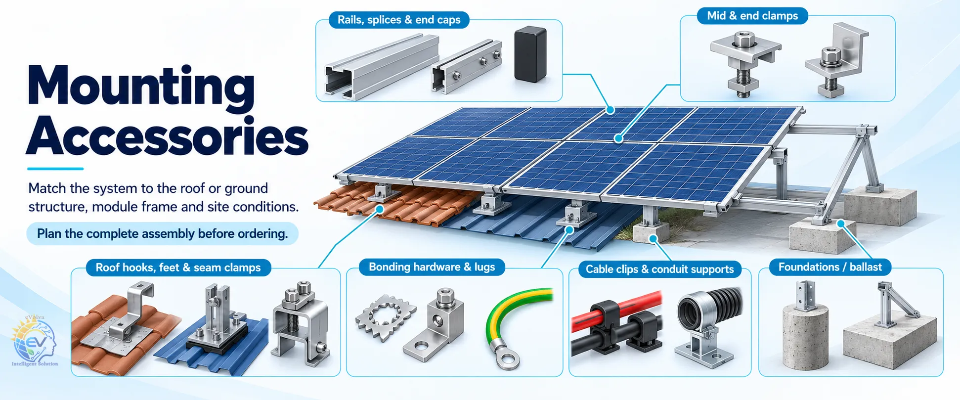
| Accessory / ပစ္စည်း | Selection checks / စစ်ဆေးရန် |
|---|---|
| Rails, splices & end caps | Compatible profiles, approved spans and expansion requirements / ကိုက်ညီသော rail၊ span နှင့် expansion |
| Mid & end clamps | Module frame thickness, permitted clamp zones and specified torque / Frame အထူ၊ clamp နေရာနှင့် torque |
| Roof hooks, feet & seam clamps | Roof-specific attachments and flashing or weather seals / အမိုးအလိုက် ချိတ်ဆက်မှုနှင့် ရေမဝင်စေရန် flashing |
| Bonding hardware & lugs | Approved bonding components and equipment compatibility / ခွင့်ပြုထားသော bonding ပစ္စည်းနှင့် ကိုက်ညီမှု |
| Cable clips & conduit supports | Outdoor suitability, cable protection and secure routing / ပြင်ပသုံးနိုင်မှု၊ ကြိုးကာကွယ်မှုနှင့် ခိုင်ခံ့သောလမ်းကြောင်း |
| Foundations / ballast | Structural design, wind loading, drainage and service access / Structure၊ လေဒဏ်၊ ရေစီးဆင်းမှုနှင့် ထိန်းသိမ်းဝင်ရောက်နိုင်မှု |
Current manufacturer portfolios
International solar panel, inverter and battery brands
Solar panels
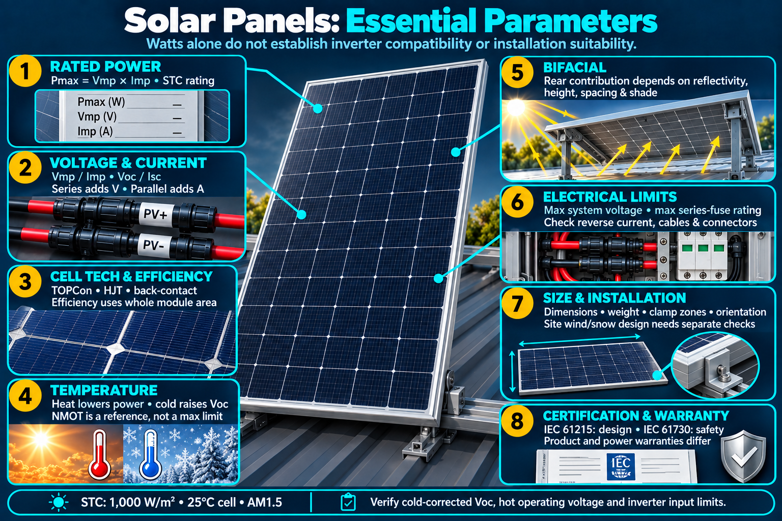
| Brand | Current family | Listed power | Best-fit planning use |
|---|---|---|---|
| LONGi | Hi-MO X6 MaxGuardian ↗ | 605–630 W | Large commercial roof |
| LONGi | Hi-MO X10 ↗ | up to 670 W | Engineered C&I / utility |
| Trinasolar | Vertex S+ ↗ | 450–510 W | Residential roof |
| Trinasolar | Vertex N ↗ | 620–725 W | C&I and ground mount |
| JinkoSolar | Tiger Neo 3.0 DG ↗ | 450–495 W class | Residential / small roof |
| JinkoSolar | Tiger Neo 3.0 utility ↗ | 650–670 W | Large C&I / ground mount |
| JA Solar | DeepBlue 4.0 Pro ↗ | Model-specific datasheet | Residential, commercial and ground-mounted arrays |
| TW Solar | Module portfolio ↗ | Model-specific datasheet | Rooftop and ground-mounted arrays |
| Qcells | Q.TRON ↗ | Model-specific datasheet | Residential and commercial roofs |
| Astronergy | Module portfolio ↗ | Model-specific datasheet | Commercial roofs and ground-mounted arrays |
Inverters — multiple international brands
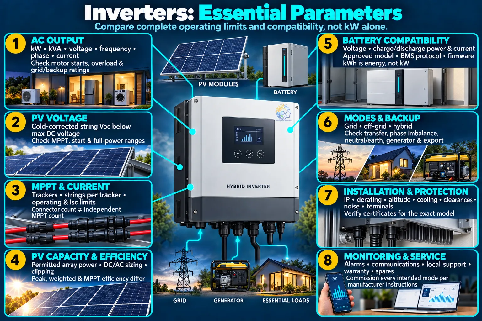
| Brand | Series | Power band | Architecture | Planning use |
|---|---|---|---|---|
| Growatt | MIN TL-X / XH ↗ | 2.5–10 kW | Single-phase grid / battery-ready | Homes and shops |
| Growatt | SPM / SPH-HU ↗ | 2.5–10 kW | Single-phase hybrid, generator-input models | Backup-focused homes |
| Growatt | MOD / MID ↗ | 3–60 kW | Three-phase grid / battery-ready models | Shops and C&I roofs |
| Growatt | WIT-HU / XHU ↗ | 4–125 kW | Three-phase hybrid with compatible HV or LV battery by model | Commercial and medium C&I |
| Growatt | SPF ES / HVM ↗ | 2–12 kW | Single-phase off-grid | Weak-grid and off-grid sites |
| Deye | Hybrid inverter portfolio ↗ | Model-specific | LV / HV hybrid models; verify phase and suffix | Homes, shops and commercial backup |
| Solis | S6 hybrid / grid-tied portfolio ↗ | Model-specific | Grid-tied and hybrid families; LV / HV by model | Residential and commercial systems |
| GoodWe | ET LV ↗ | 5–20 kW | Three-phase hybrid with low-voltage battery | Residential and small commercial backup |
| Huawei | FusionSolar inverter portfolio ↗ | Model-specific | Grid-tied / storage-capable models; approved ESS required | Residential and commercial roofs |
| Sungrow | String / hybrid portfolio ↗ | Model-specific | Grid-tied and hybrid families; model-specific batteries | Residential, C&I and larger projects |
| MUST | PV1800 / inverter portfolio ↗ | Model-specific | Off-grid and storage models; verify grid operation | Backup and off-grid sites |
| Sigenergy | SigenStor ↗ | Model-specific | Integrated inverter and modular storage system | Residential and commercial storage |
Batteries and energy storage
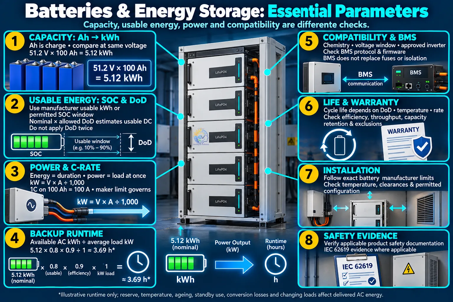
| Brand | Family / manufacturer link | Energy and voltage | Selection checks |
|---|---|---|---|
| Growatt | APX / ARK ↗ | Model / module-count dependent | Modular storage; match the approved inverter series |
| Deye | RW / SE families ↗ | Model / module-count dependent | LV storage options; verify BMS and parallel limits |
| Dyness | DL5.0C / storage portfolio ↗ | Model / module-count dependent | Check the exact inverter compatibility list |
| MUST | Lithium battery portfolio ↗ | Model / module-count dependent | Check nominal voltage, continuous current and BMS |
| Sigenergy | SigenStor battery ↗ | Model / module-count dependent | Integrated modular ESS; use the matching controller |
| GoodWe | Lynx battery portfolio ↗ | Model / module-count dependent | Select the battery approved for the inverter family |
| Huawei | LUNA2000 ↗ | Model / module-count dependent | Use the compatible FusionSolar storage configuration |
| Sungrow | Residential storage portfolio ↗ | Model / module-count dependent | Use the model-specific inverter / battery combination |
These are manufacturer-listed product families, not a statement of Myanmar warehouse stock. Obtain the exact suffix datasheet, serial traceability, authorized-channel evidence and inverter–battery compatibility letter before purchase.
Myanmar market references: the linked financing and supplier lists show local brand presence. Product families are examples; confirm the exact available model, warranty support and inverter–battery compatibility before ordering.
Battery-first design
Choosing the right battery
Choose LiFePO₄ for most solar storage systems. Consider flooded lead-acid batteries when the project’s budget, operating needs and maintenance arrangements justify them.
Battery energy (kWh), battery power (kW), inverter voltage and the BMS protocol must all match. Brand name alone does not prove compatibility.
Tap any block for an illustrated explanation. This is a functional overview; power and communication use separate paths.
- Typically 80–90% usable depth of discharge, subject to warranty
- Integrated BMS, higher cycle life and no routine electrolyte topping
- Prefer IEC 62619 evidence, UN 38.3 transport evidence and an inverter compatibility list
- Lower initial cost can suit basic off-grid or essential-load systems
- Requires ventilation, upright acid-resistant containment and safe service access
- Needs electrolyte-level checks, correct charging and corrosion control; never install in living or escape areas
Balance of system
DC, AC, earthing and protection accessories
Protection devices must be selected from voltage, current, fault level, earthing arrangement and cable calculations—not copied from a generic bill of materials.
DCDCDCAC
Tap a block for its illustrated explanation. DC becomes AC inside the inverter. This is a functional overview, with separate PV and battery circuits.
PV cable and matched connectors; coordinated string and battery protection, DC isolation, PV-rated surge protection, labels and cable containment. Select a device below for its role and checks.
Coordinated MCB/MCCB, AC isolation, AC surge protection and the required RCD/RCBO type; voltage/current monitoring, approved transfer arrangements and metering as the design requires.
PE cable, bonding hardware, the main earth terminal and electrodes form part of the protective system. Coordinate the lightning design and SPDs, then verify continuity, electrode performance and protection.
Representative manufacturers to evaluate include ABB, Schneider Electric, CHINT, DEHN and Phoenix Contact. Select only model-specific DC/AC ratings and request coordination evidence; this is not an endorsement or stock confirmation.
Monthly solar resource
Myanmar solar radiation and availability map
Select a month to compare long-term average daily global horizontal irradiation (GHI) at 25 representative cities. The map shows Myanmar's 14 state and region boundaries.
25-city range5.27–6.65kWh/m²/day
Approximate interpolation between 25 cities; not a measured radiation raster.
3.07.0 kWh/m²/day
Yangon
Monthly average daily GHI · kWh/m²/day
Selected monthkWh/m²/day
Annual irradiationkWh/m²/year
Strongest month
Monthly values
Long-term averages, not a weather forecast or PV electricity output. Click a city on the map or list to compare its seasonal pattern.
Compare 25 cities · selected month
Myanmar pattern
February–April is generally strongest. Monsoon cloud lowers GHI most noticeably from June–August, especially in coastal and southern areas; central Myanmar remains comparatively stronger.
Daily PV energy ≈ installed kWp × monthly GHI × performance ratio
For example, 5 kWp × 4.0 × 0.78 ≈ 15.6 kWh/day. A more accurate estimate also needs panel tilt, orientation, shading, temperature and system losses.
These are 2001–2020 monthly averages, so they represent typical seasons rather than this year’s weather.
Monthly GHI matrix — kWh/m²/day
Solar source: NASA POWER 2001–2020 climatology, ALLSKY_SFC_SW_DWN. Annual total is calculated as each monthly average daily GHI multiplied by the number of days in that month and summed for a 365-day year. Magway and Chauk share the same NASA climatology grid cell. Boundary source: geoBoundaries gbOpen, Myanmar ADM1 (14 units, 2019), CC BY 4.0. Use site coordinates, shading analysis and a bankable energy model for investment decisions.
COMMERCIAL
Solar products and services
Advertising opportunities for solar businesses, alongside a free supplier directory.
Products & Accessories
Promote panels, inverters, batteries, protection devices and installation accessories.
No sponsored listings yet. Advertising enquiries and booking will be available here when launched.
System Integrators
Featured business profiles for system design, EPC, commissioning and maintenance services.
No sponsored listings yet. Advertising enquiries and booking will be available here when launched.
Installers
Promote installation services by service area and residential or commercial expertise.
No sponsored listings yet. Advertising enquiries and booking will be available here when launched.
Paid listings will be labelled Sponsored. Payment does not imply technical endorsement. Basic directory listings remain free.
Free Directory
Myanmar solar suppliers and service providers, listed alphabetically by company name.
Arkar Min Thu Kha ↗
Solar systems, circuit protection devices and battery backup equipment.
KZH Engineering & Trading ↗
Solar equipment and batteries, with local sales and service hotlines.
Myanmar Eco Solutions ↗
Mounting structures, solar equipment and system installation.
Myanmar Solar Power ↗
Solar supply, rooftop installation and EPC services.
Radiant Rays ↗
Solar material supply, engineering, installation and maintenance.
Shwe Kabar Energizers ↗
Mounting rails and accessories, including mid clamps; solar installation projects.
Yaung Ni Oo Electric ↗
Solar assessment, design, installation and long-term support; electrical product supply.
No matching businesses. Try another search or clear the filters.
Reference examples only. These are not paid advertisements or commercial directory listings.
Procurement map
Sample suppliers and manufacturers
Myanmar suppliers and EPC firms
- Myanmar Solar Power TradingEPC, rooftops, JA Solar, Growatt, Sungrow, Huawei and other partners listed
- Great United Green EnergyMyanmar distributor and installer; Sigenergy and EENOVANCE authorization stated
- KZH Engineering & TradingSolar supply and service presence in Yangon, Mandalay and Nay Pyi Taw
- IME InternationalDeye solar business presence in Yangon and Mandalay
- Good BrothersSolar, inverter, battery and power-station product categories
- Indigo EnergyMyanmar solar EPC, project development and O&M services
- JJ-PUNCustomized renewable-energy systems and local technical services
- Shwe Taung Solar EnergyIntegrated solar investment, installation and operation
Southeast Asia channels
- BayWa r.e. Solar DistributionRegional modules, inverters, storage, racking and logistics
- EnphaseMicroinverter and battery channel in Malaysia, Vietnam, Thailand and the Philippines
- LONGi, Trina Solar, JinkoSolarMajor module manufacturers with APAC distribution
- GoodWe, Sungrow, SolisResidential and commercial inverter and storage portfolios
South Asia channels
- Waaree EnergiesIndian modules including 600–635 W N-type and a listed 700 W product
- Tata Power SolarModule manufacturing and nationwide rooftop EPC network in India
- Adani SolarVertically integrated Indian module manufacturing
- Vikram Solar, RenewSysIndian module manufacturers for regional tender evaluation
This directory is a procurement starting point, not an endorsement or proof of current stock. Confirm authorized status, model-specific certificates, serial traceability, warranty owner, spare parts, commissioning support and references before purchase.
Engineering and safety
Minimum design and commissioning controls
- Survey and load auditMeasure interval demand, motor surge, roof condition, shade, cable routes, earthing and generator behavior.
- Structural and weather designCheck wind uplift, corrosion, waterproofing, drainage, maintenance access and monsoon exposure.
- Electrical studyVerify Voc at minimum temperature, MPPT current, cable ampacity, voltage drop, fault level, discrimination and phase balance.
- Protection and isolationUse coordinated DC and AC isolators, fuses or breakers, Type 2 SPDs, RCD protection where applicable, labels and emergency shutdown.
- Battery room controlsProvide restricted access, non-combustible mounting, ventilation per manufacturer, temperature control, clearances and fire response planning.
- Testing and handoverRecord polarity, insulation resistance, continuity, earth resistance, inverter settings, BMS communications, backup transfer and as-built drawings.
Reference standardsIEC 61215, IEC 61730, IEC 62548-1, IEC 60364-7-712, IEC 62109, IEC 62619, IEC 62930, IEC 61643 and IEC 62305. Apply current Myanmar authority, utility and fire requirements where they are stricter or project-specific.
Sources and update notes
Technical and supplier information checked 15 September 2026. Use manufacturer datasheets for the exact model purchased.